
Start with the assembly problem
A shield that covers one circuit area, a removable frame-and-lid assembly and a compartmented shield have different design priorities. A useful custom manufacturing brief explains the available PCB space, mating parts and installation sequence before it fixes the outer dimensions.
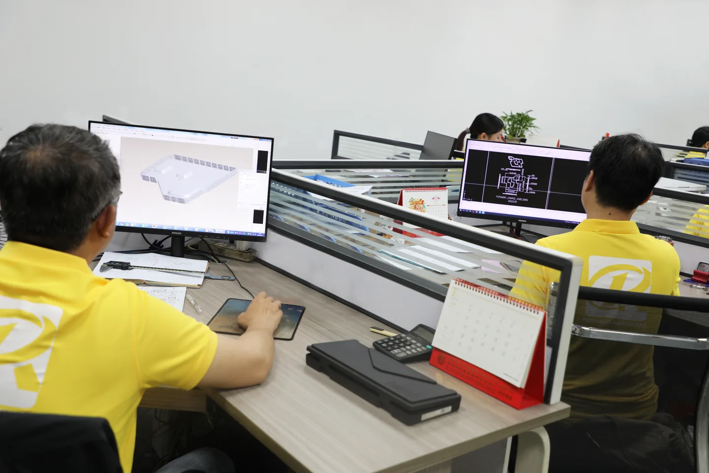
Ruishuo reviews customer drawings for metal shielding cases, frames, covers and supporting hardware. Existing product photographs can help communicate the structural direction; the project drawing and approved sample establish the dimensions, material and acceptance requirements.
Choose a structure for the way the product is assembled
Single-body shield
Identify whether components need to remain accessible after installation. Define the internal height, component keep-outs, purpose of openings and the board attachment interface.
Frame with removable lid
Specify frame attachment and lid retention separately. Check the opening direction, removal access and nearby components against the complete PCB assembly.
Multiple cavities and supporting hardware
Locate partitions against the circuit layout. Define which frames, lids and clips are supplied together and which mate with customer-owned parts.
Separate fixed requirements from reviewable options
Mark the features that cannot move: an existing PCB land pattern, a connector opening or a height restriction imposed by the enclosure. List material, forming and packaging options that remain open to discussion. This keeps manufacturing feedback focused on changes the design can accept.
| Project input | Include in the brief | What it helps define |
|---|---|---|
| Circuit and space | Coverage area, PCB, components and enclosure constraints | Shield arrangement, height, openings and access |
| Drawing control | 2D/3D files, units, revision and critical datums | Quote scope, tooling inputs and sample assessment |
| Material and finish | Base metal, grade, thickness and treatment requirements | Forming, soldering, contact surfaces and inspection |
| Quantity and validation | Sample quantity, initial batch and checks required | Sample route and production preparation |
| Packaging and schedule | Assembly supply, labeling and approval milestones | Packaging review and delivery planning |
Move from review to a controlled production revision
Agree the inputs
Confirm the drawing revision, coverage area, mating parts and units. If starting from a physical sample, identify the functions and features that must be retained.
Review manufacturing constraints
Discuss the material, holes, bends, formed depth and assembly conditions. Record proposed changes and customer approvals against the same drawing revision.
Define the paid sample
Agree whether the sample will validate geometry, fit, a finish or a production-related feature. State which conclusions require further checks on the final manufacturing route.
Approve production inputs
Bring the drawing, material, inspection and packaging specifications into one approved version before confirming volume production arrangements.
Prepare a project that can move forward
A complete design is not essential for the first discussion. Send the current drawing or a structural sketch, expected quantities and the questions you need help resolving. For confidential designs, discuss the NDA and information scope before sharing sensitive files.
Samples are charged. Standard samples take 3–5 days, expedited sampling is 48 hours, and tooling with sample production takes 7–10 days under the confirmed sample plan. These schedules cover the sample stage; volume production and delivery are reviewed separately.