
Shielding references for real design decisions
Review formed geometry, process sequence and the final condition of functional surfaces.
6 product references shown
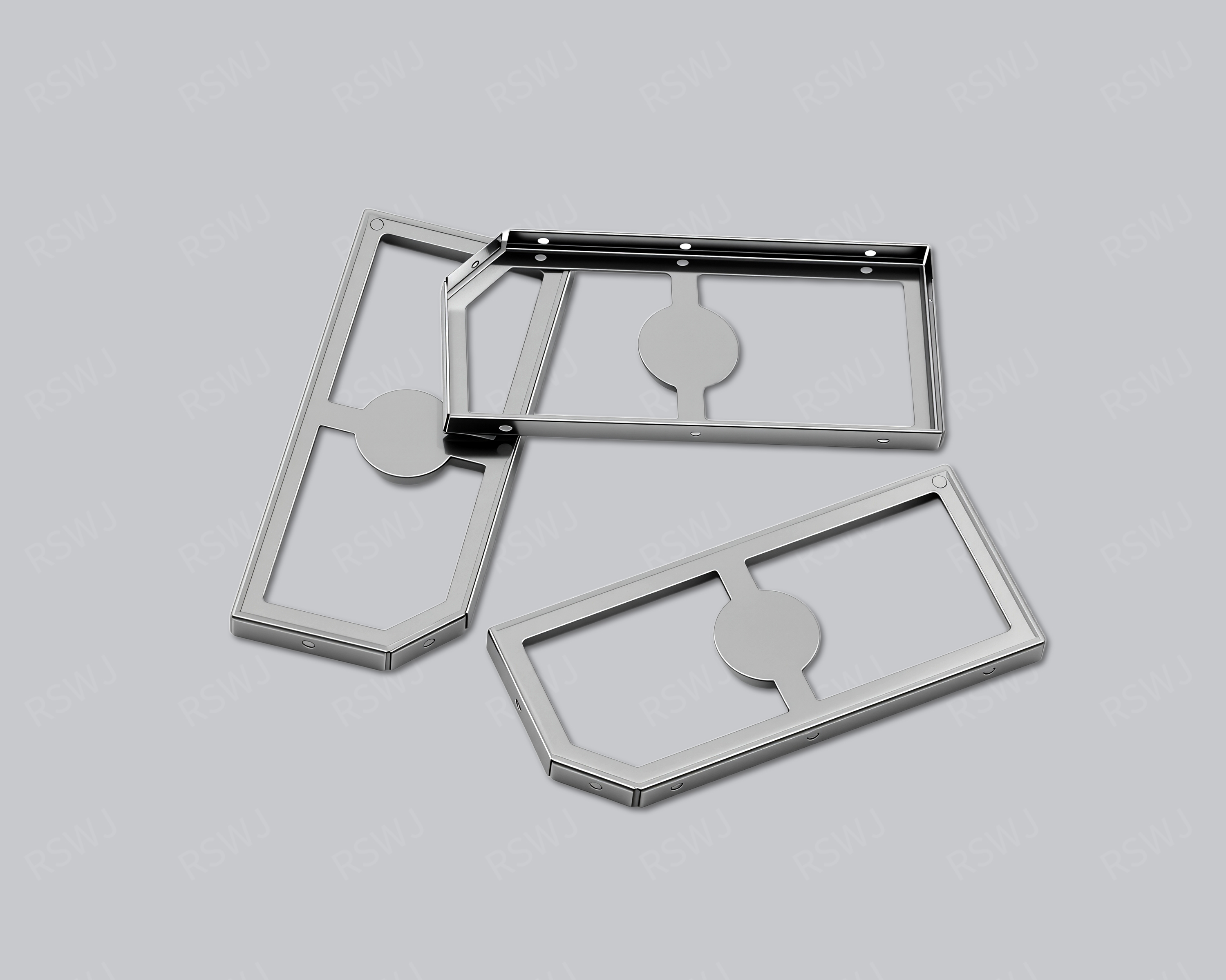
SMT Shielding Can
An SMT shielding structure connects local coverage with surface-mount placement and attachment.
Explore the product & design →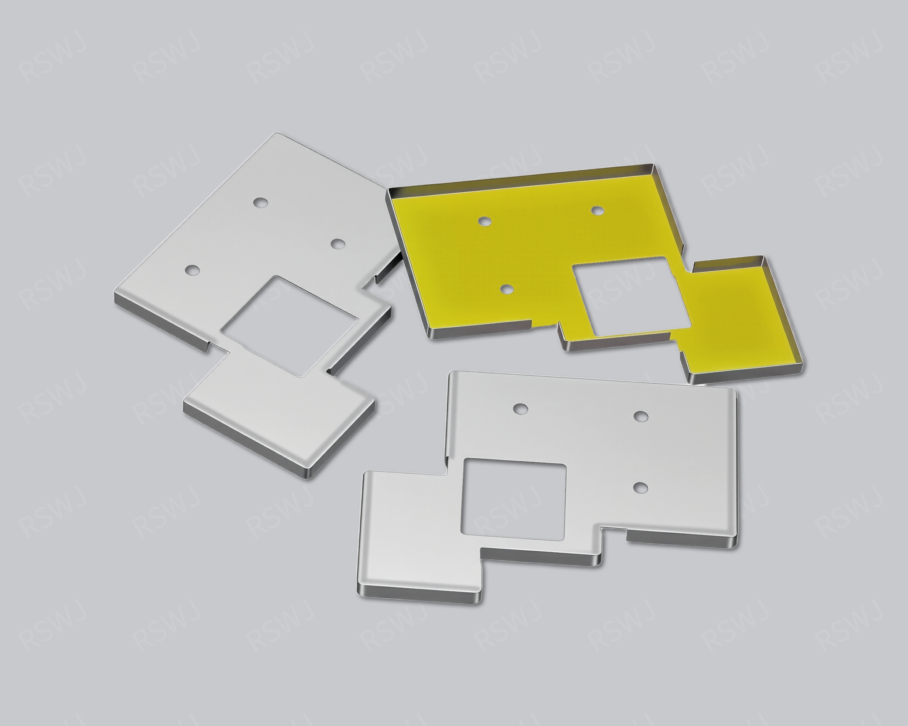
Stamped Shielding Can
A stamped shielding can converts sheet geometry into blanking and forming operations around finished-part datums.
Explore the product & design →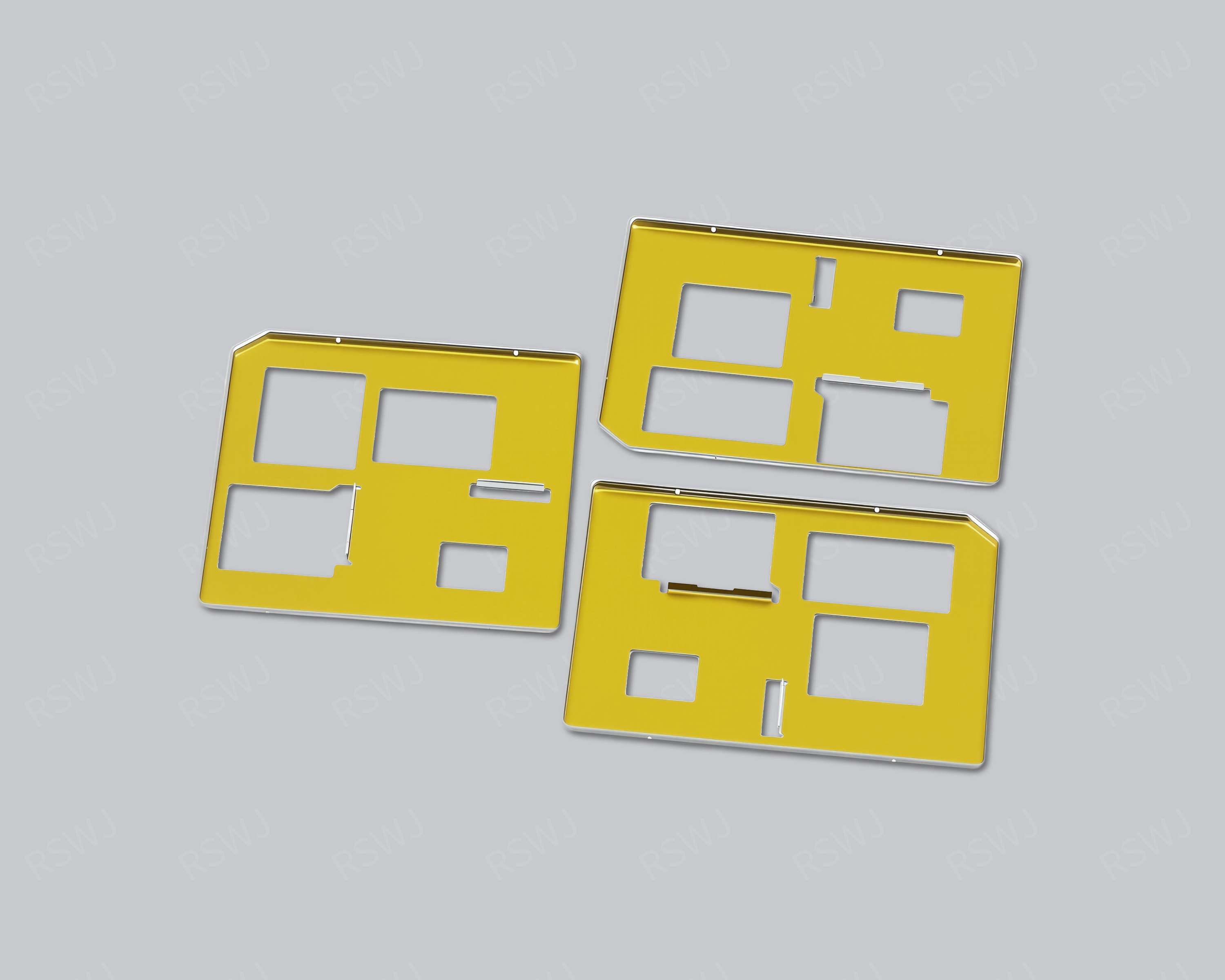
Deep-Drawn Shielding Can
A deep-drawn can develops a roof and sidewall contour through sheet forming, with trimming and interfaces defined afterward.
Explore the product & design →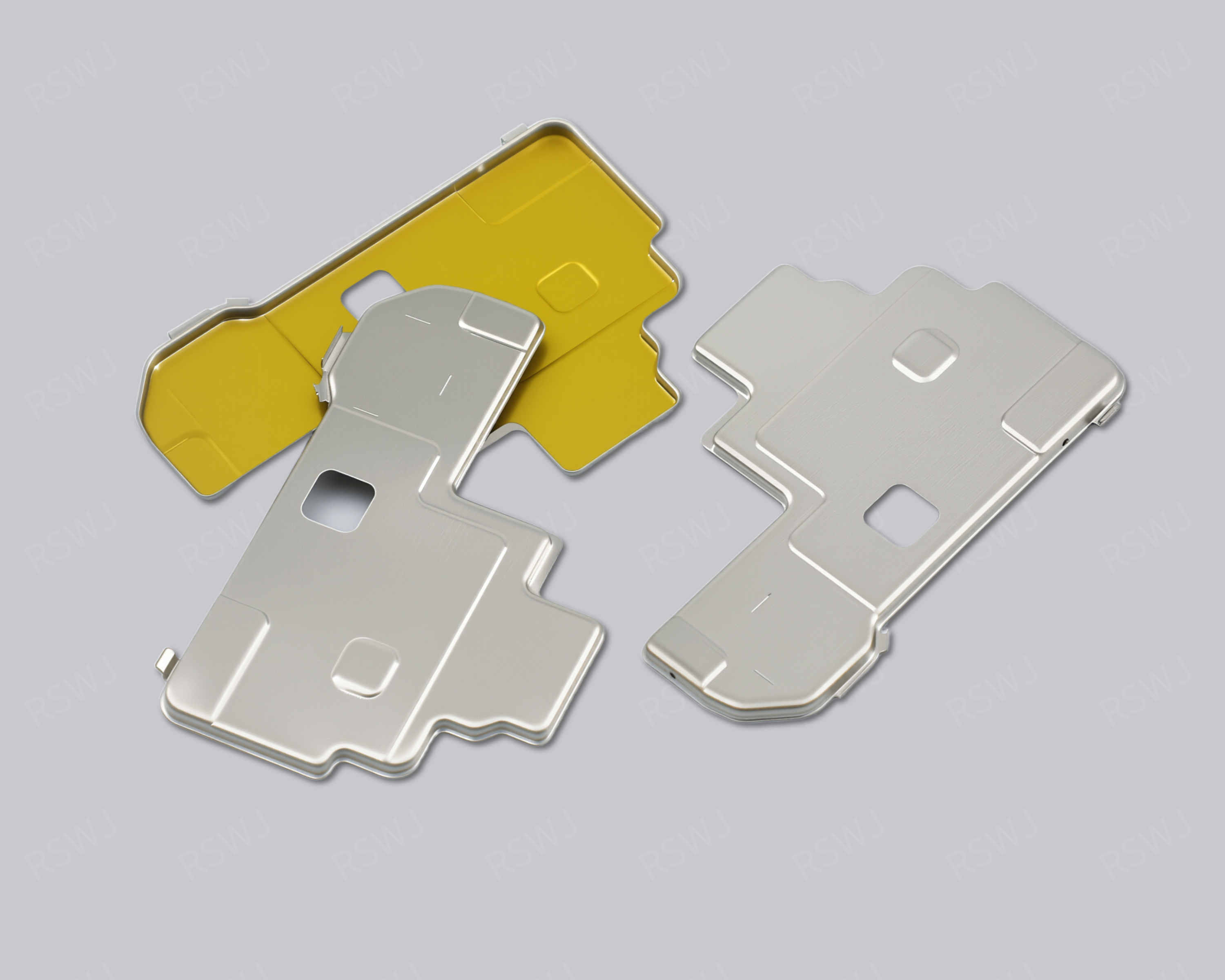
Insulating Paint Shielding Can
A shield with insulated areas separates electrical-isolation regions from retained conductive attachment and contact.
Explore the product & design →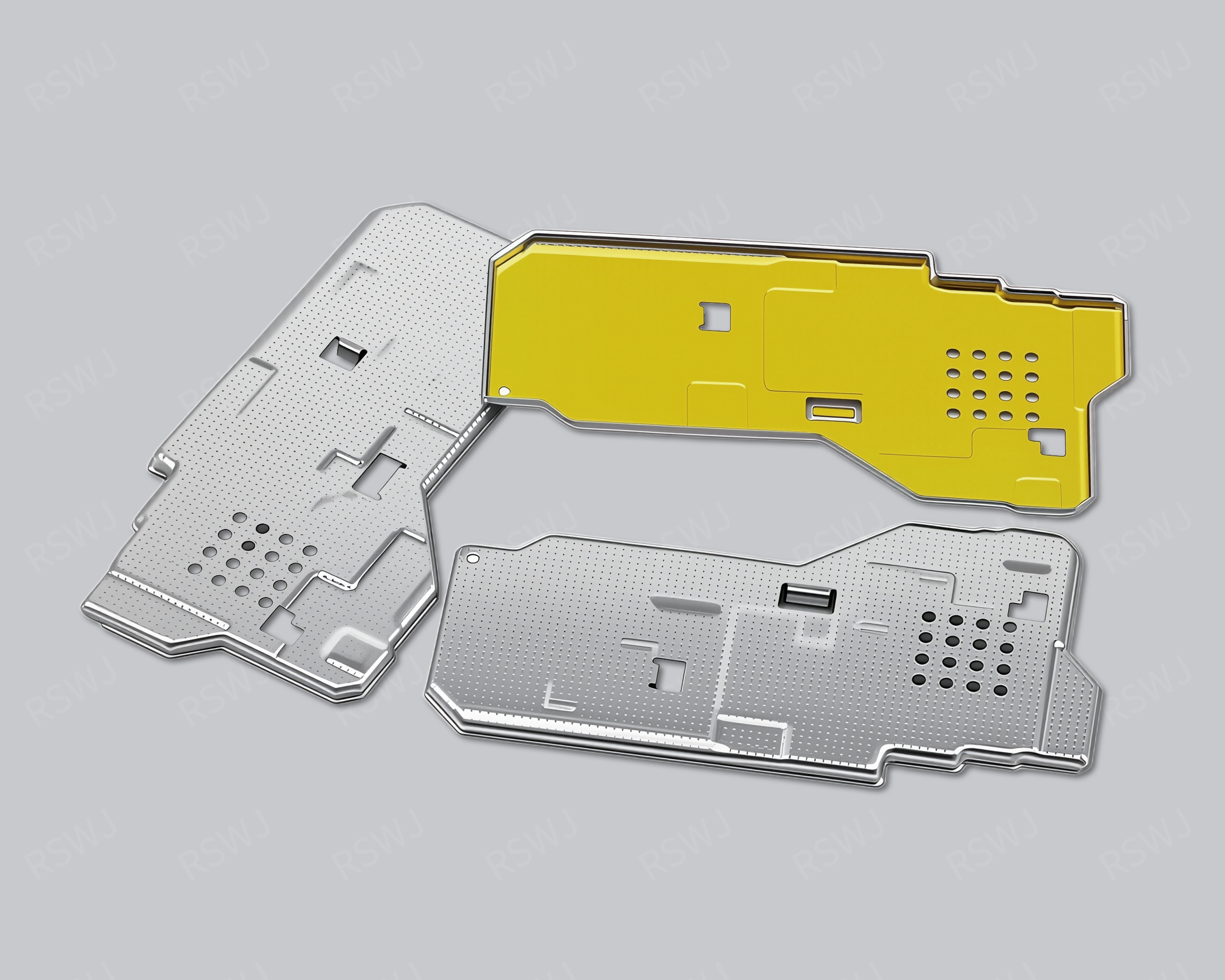
Tin-Plated Shielding Can
A tin-plated can specifies a final surface requirement alongside the base material and closure geometry.
Explore the product & design →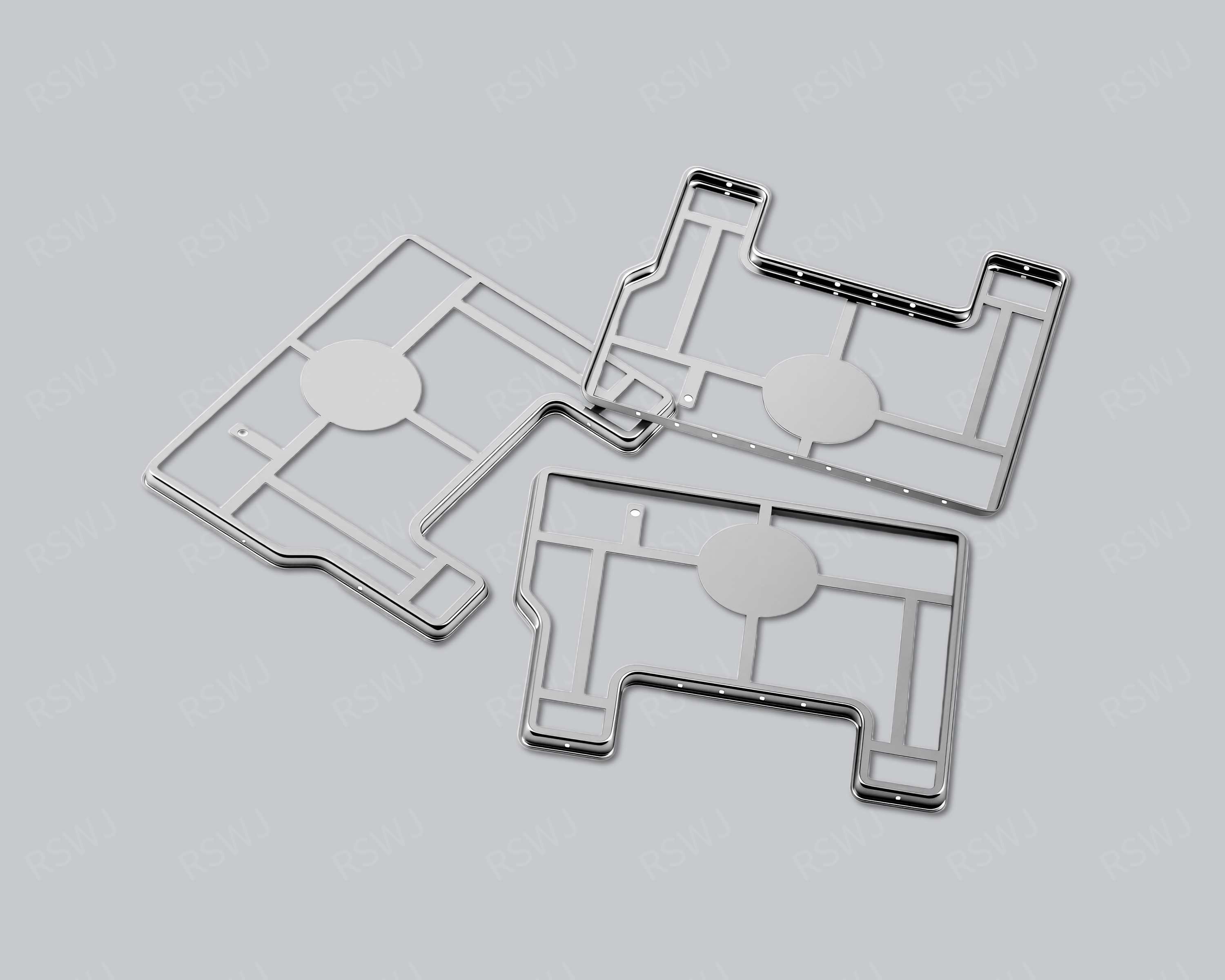
Nickel-Plated Shielding Can
A nickel-plated can connects a specified substrate with a required final surface and mating condition.
Explore the product & design →Review the final part and its process state
Forming and finishing choices follow the agreed geometry, substrate and interfaces. Identify finished-part datums, functional edges and treatment regions. Bare-part inspection, the customer assembly operation and system evaluation establish different conditions and should remain distinct.
Define the sample before comparing it
Provide the drawing revision, material, mating components and required acceptance checks. Samples are chargeable. Reference planning is 3–5 days for standard samples, 48 hours for expedited sampling, and 7–10 days for tooling and sample production. These arrangements exclude mass-production delivery; the actual project scope and timing are reviewed separately.
Discuss the drawing package