
Define the part in its finished assembly condition
Manufacturing review starts with the shield geometry and the way it meets the assembly. Define the finished-part datums, internal space, mounting features, openings and edges that engage the PCB or lid. The die concept should support those relationships rather than only the external CAD outline.
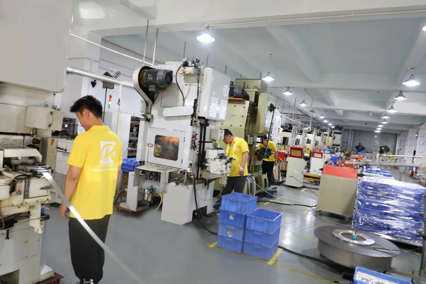
Ruishuo manufactures shielding parts and precision hardware through project-specific stamping and forming plans. Deep drawing and sample routes are reviewed against the geometry, material and quantity. One-piece, two-piece and multi-cavity describe the structure; they do not prescribe one universal process.
Bring the right features into the process review
| Manufacturing topic | Key inputs | Review outcome |
|---|---|---|
| Precision stamping | Holes, edges, bends, flanges, mounting features and thickness | Finished dimensions, burr direction, datums and assembly clearance |
| Deep drawing | Depth, corners, internal envelope, material and openings | Forming regions, trimming or piercing requirements and usable space |
| Tooling concept | Drawing revision, controlled dimensions and production requirements | Approved tooling inputs, trial checks and change records |
| Sample route | Validation purpose, mating PCB or parts and acceptance method | Clear sample scope and items to recheck in production |
| Surface finishing | Base metal, treated areas, soldering and contact interfaces | Final mating dimensions, surface condition and inspection scope |
Develop tooling against the inspection requirement
Die development needs the same critical-feature definition as inspection. Hole locations, attachment edges and lid interfaces should be related to the drawing datums and an agreed checking method. If acceptance applies after finishing, that final condition belongs in the manufacturing inputs.
Ruishuo has in-house die-making capability, with factory output of more than 100 die sets per month and more than 20 precision stamping presses. These factory capabilities support project review; the die type and production arrangement are selected for the actual part.
Geometry and fit
Separate free-state part dimensions from installed fit. Identify the PCB, frame, lid or fixture required for assembly validation.
Material and final surfaces
Record the base metal, thickness and treatment. Mark surfaces involved in soldering, electrical contact or mechanical engagement.
Inspection and supply
Establish measuring datums, appearance criteria and packaging orientation before the process and supply arrangements are approved.
Maintain a revision chain from trial parts to production
Drawing review
Confirm the geometry, manufacturing constraints, critical dimensions and governing files. Record customer approval of proposed changes.
Tooling or sample preparation
Choose the route that matches the sample purpose and identify the required dimensional, material and assembly checks.
Sample feedback
Describe the issue in its assembly condition and locate the affected feature on the drawing. Recheck the consequences of each revision.
Production and packaging inputs
Approve the drawing, material, inspection, quantity, labeling and assembly supply requirements together.
Plan timing against a defined scope
Samples are charged. Standard sampling is 3–5 days, expedited sampling is 48 hours, and tooling with sample production is 7–10 days under the agreed plan. These are sample-stage schedules and exclude volume production and delivery.
Volume delivery is reviewed against the order quantity, material, tooling, finish, inspection and packaging. State sample demand and production demand separately in the RFQ so each stage receives the correct manufacturing scope.