
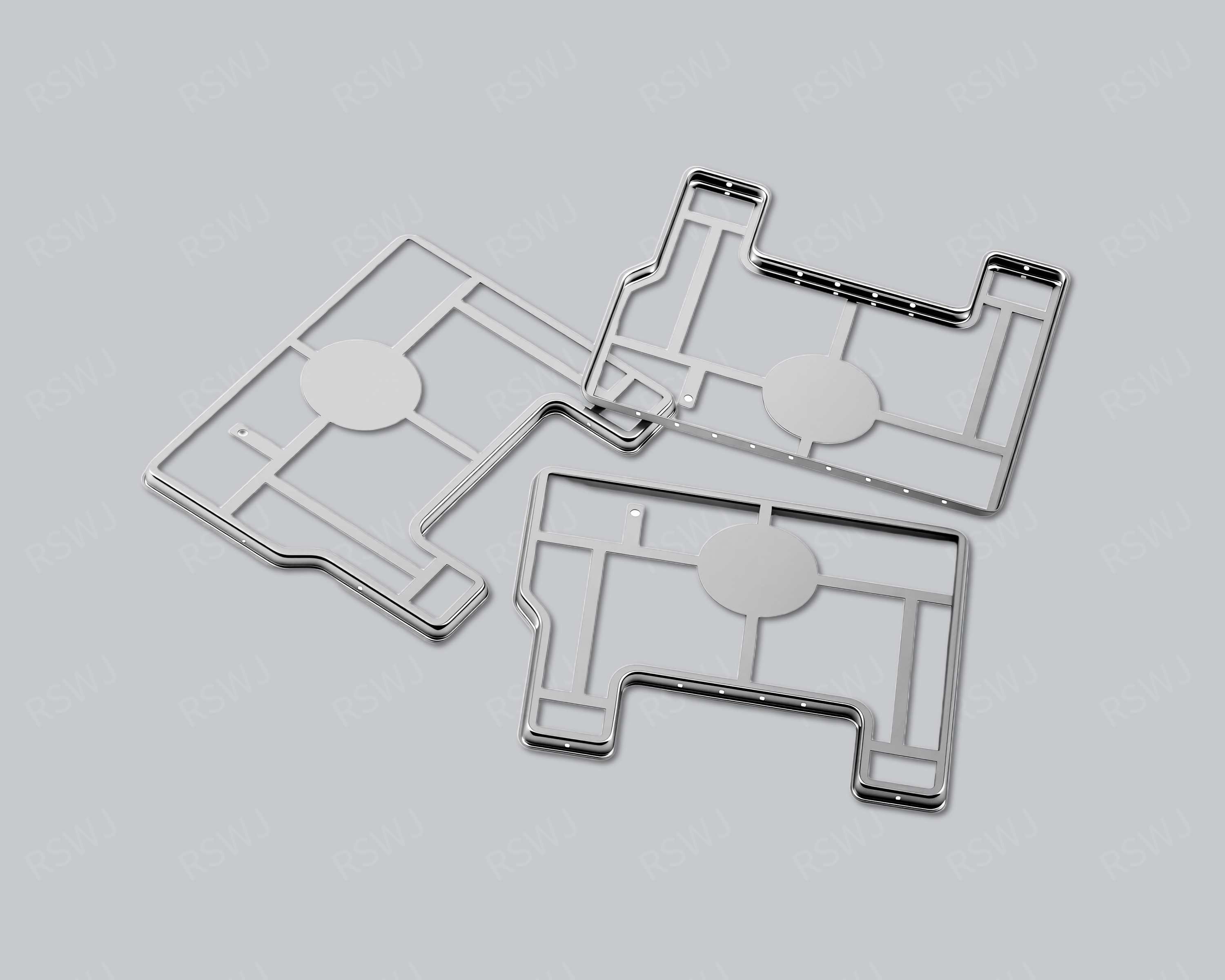
Reference photograph. Material, dimensions and mating requirements are defined in the agreed project drawings.
Fit and contact after nickel plating
A nickel-plated can connects a specified substrate with a required final surface and mating condition.
| Design focus | Substrate, nickel specification, selective regions and final fit |
|---|---|
| Project task | Fit and contact after nickel plating |
| Custom inputs | Current drawings, mating parts, material and final surface, quantity and acceptance requirements. |
Fit and contact after nickel plating
The finish name does not define the full coating specification or its suitability for a joining process. Functional areas and verification need explicit requirements.
The plated cover should be accepted in its final condition against the matching parts. Specify the substrate and treatment version, then identify the dimensions and surfaces that affect closure or attachment. If joining or environmental conditions matter, state those project inputs separately. Inspect fit after processing rather than applying a bare-part measurement as the whole verdict. This makes the coating discussion actionable without inferring composition, thickness or test performance from the sample photograph.
Engineering considerations for this project
Locate the dimensions governing fit after nickel treatment
A nickel-plated cover should be accepted against the dimensions and surfaces that establish its final mating relationship. Identify the working edges, seating references and closing partner in the customer’s drawing. A general outside-size check may not describe the local feature that controls assembly. State which requirements apply after treatment and keep any intermediate process measurements distinct. This gives the manufacturer an inspection target tied to the delivered component and prevents a bare-part observation from being used as the complete acceptance evidence when the customer has specified a different final-surface condition for the cover.
Specify the substrate and the nickel-treatment requirement separately. The finish name does not establish the underlying material, a treatment composition or its required scope. Identify any regions that need selective processing, retained contact or a customer-defined joining condition. A visually consistent surface can still leave those functional boundaries unspecified. Locating them explicitly makes the treatment discussion actionable and allows engineering to consider a processing proposal against the actual mating features instead of assuming that the example photograph describes the complete material and surface specification of the ordered part.
Check closure and attachment using the finished sample
Trial the finished component with the actual mating references, examining the operation that seats or retains it. Identify the surfaces used to position the cover and the local regions approached by tools or partner features. If the surface state after that operation matters to the project, inspect the relevant regions in the assembled condition as well as before installation. Keep those observations separate from any customer-defined electrical or environmental evaluation. The manufacturer’s final-fit check describes how the processed component relates to its partner; it does not establish an unrelated performance result from the nickel-plated appearance.
Localize a fit issue before revising the requirement. Mark whether the observation concerns the finished working edge, the partner geometry, the seating operation or another defined interface. Compare it with the corresponding drawing and assembly state. A broad instruction to improve nickel-plated fit does not indicate whether the change belongs to geometry, treatment scope or the mating arrangement. A controlled sample comparison can keep the substrate and contour fixed while the relevant treatment condition is reviewed, or identify a separate geometry proposal when that is the actual variable. This makes the resulting decision more useful for manufacturing and procurement. Retain identifiers for both the treated cover and its matching partner during the fit trial; this makes a local closure observation traceable when several surface or partner revisions coexist.
Keep surface alternatives and partner revisions distinguishable
When considering a treatment alternative, state the purpose and the customer’s required final condition. A change proposed for processing or appearance may also require reassessment of a contact or mating region, so identify those affected functions. Keep the partner revision and the component geometry recognizable in the trial. If the mating part changes at the same time, label the combined change instead of assigning the result to the cover’s surface alone. This gives the customer a clear basis for deciding which evidence supports the selected final-state specification and which relates to another part of the assembly.
An order package should identify the substrate, nickel-treatment requirement, selective regions where applicable, drawing revision and final-fit checks. Include the mating information used to accept the sample and any customer-defined joining or environmental requirements as explicit conditions. Where a specification is still open, mark it for review rather than replacing it with an unsupported general coating claim. These inputs connect the nickel-plated reference with a defined finished component and working interface. They also make future surface or partner changes traceable without inferring treatment thickness, composition or durability from the image of a metal part.
Boundary, clearance and mating design
Review closure and contact after treatment. Locate selective-processing boundaries from datums visible on the final component.
A process request should begin with the finished component and its installation. Show the coverage, attachment and required interfaces before selecting the operation sequence. A forming or finishing name describes part of manufacture, not the full shielding boundary. Openings, seams and mating features still need a relationship with the actual circuit. Review what each feature does and where it sits so that a process alternative preserves the intended assembly rather than merely producing a similar outline.
Material and final surface definition
Provide the substrate grade, supply condition and thickness with the geometry. Forming and final treatment are connected but different inputs. Prefinished stock and processing after forming may need a different sequence; identify the intended delivered state and the surfaces used for joining or contact. The process label does not provide a coating parameter or a material identity. Those requirements must remain explicit and traceable to the project drawing package.
Forming and the installation sequence
Agree forming, later operations and finishing as one route. Soldering or environmental requirements use actual project conditions.
Define critical features on the formed, trimmed and finally treated part. The datum scheme should be usable in inspection and meaningful for the installation. A dimension on an intermediate blank can help manufacture without replacing the acceptance dimension of the finished component. Identify the relation between bends, openings and the attachment edge. If a later operation changes a functional location, inspect that final location rather than accepting only the preceding forming step.
The finished mating condition drives acceptance
Compare nickel-finish proposals with the same substrate and functional geometry where possible. State treatment requirements explicitly and identify regions involved in closure, contact or joining. The inspection should use final-part dimensions and matching components after treatment. If an environmental or assembly condition matters, define it as a project input rather than assuming it from the finish name. This keeps the decision focused on a usable interface.
Part inspection and application evaluation
Inspect finished dimensions and surfaces with matching parts. Retain the coating version when comparing sample changes.
A drawing package for this custom part
| Input | What makes it usable |
|---|---|
| Coverage & interfaces | Substrate, nickel specification, selective regions and final fit. Mark their relationship with the actual circuit or mating layout; identify fixed references and permitted changes. |
| Final part & datums | A dimensioned finished-part drawing and available 3D information. Identify functional dimensions, the installed condition and the measurement references used to accept them. |
| Material & surface | The specified grade, condition, thickness and final treatment. Show contact, joining and insulated regions separately; identify any alternative that needs evaluation. |
| Assembly & acceptance | Corresponding mating revisions and the installation or access sequence. Distinguish part inspection, matched fit and customer system checks with their agreed conditions. |
Questions for this design review
How is a selective plating requirement made inspectable?
Locate the boundary from identifiable datums and show which regions are processed, preserved or separately controlled. State the final surface requirement and method used for acceptance. Check the mating assembly after processing. The photo can help locate the intended area but cannot establish layer parameters or prove a process version, so retain the specified treatment and sample records with the dimensional result.
Which drawings support the review of Nickel-Plated Shielding Can?
Use the current layout and mating assembly to identify substrate, nickel specification, selective regions and final fit. Mark the relationship that is already fixed and the specific feature being considered for change. A drawing of the cover alone may omit the condition that gives the reference its engineering purpose. Include the corresponding board or base and the intended operation so the proposed revision can be evaluated against a defined task rather than a similar-looking external shape.
In-House Tooling & Formed-Part Quality
Tooling development and forming quality
The manufacturing review for Nickel-Plated Shielding Can connects how critical features are formed, how they are inspected and how they meet the mating assembly. Ruishuo links in-house die design and CAD/CAM simulation with stamping. Die-making output of more than 100 sets per month is a factory capability; the tool concept is reviewed for the actual project.
Formed geometry and the treated working surface
Separate the base-metal geometry formed by the die from the surfaces in the final treated condition. Openings, engagement details and local insulated regions may have different acceptance requirements. Record the operation sequence, treatment boundaries and final fit in one drawing revision.
- Before and after treatment
- State base-metal dimensions, treatment areas and final acceptance dimensions. Check location and closure in the delivered sample condition.
- Functional surface boundaries
- Identify grounding, soldering, engagement and insulation areas separately. Assess the actual fit and contact requirements after treatment.
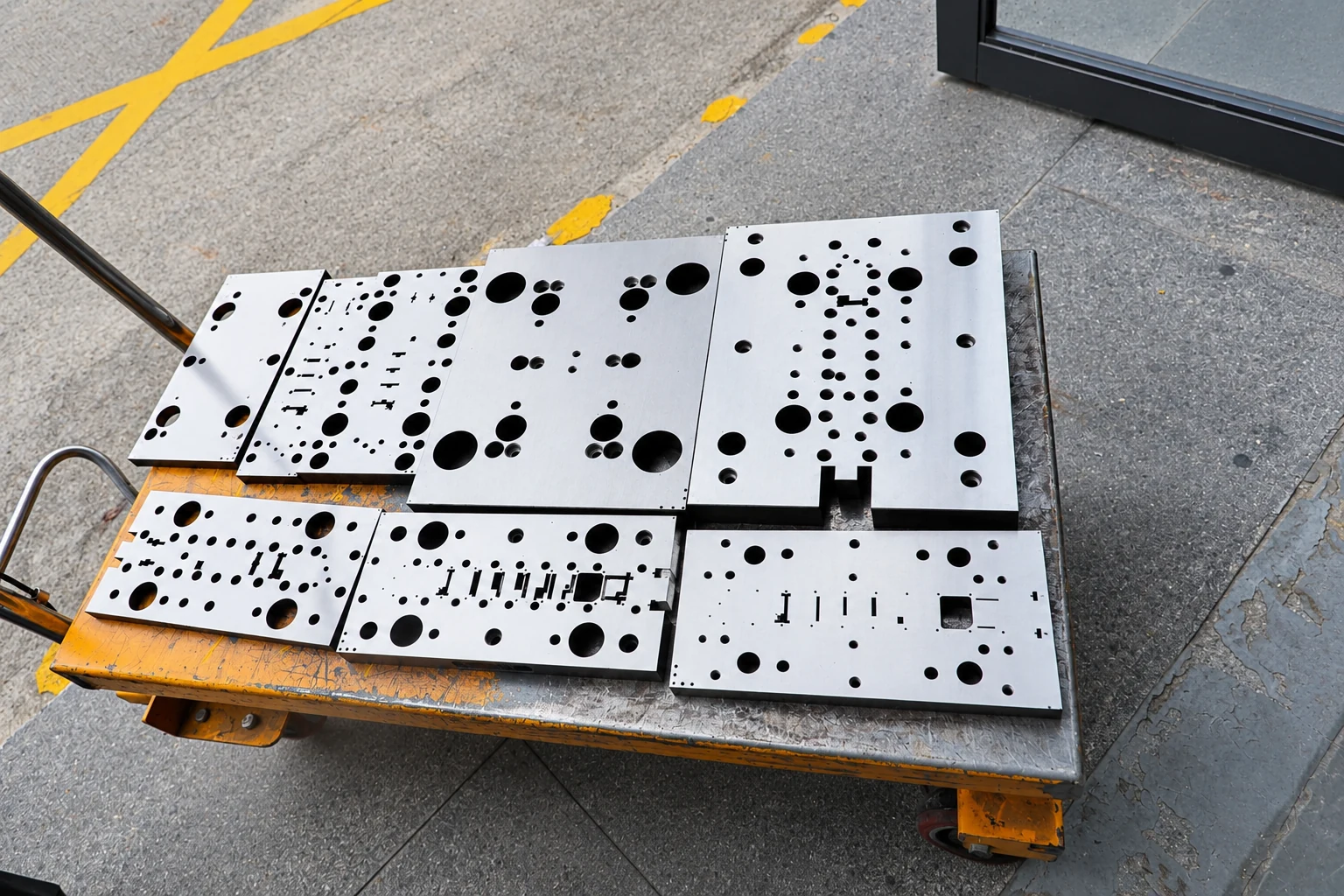
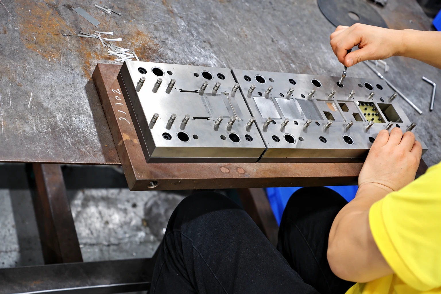
Paid samples include a full dimensional inspection report. Define drawing datums, acceptance criteria and corresponding mating parts so measurement and installed-fit checks can each answer the correct question. Confirm the charges, responsibilities and revision requirements for design changes, tooling work and later production stages within the project scope.
Paid samples and project planning
Samples are chargeable. Reference planning: standard samples 3–5 days; expedited sampling 48 hours; tooling and sample production 7–10 days. These are sample-stage arrangements, excluding mass-production delivery. The project plan is reviewed against the confirmed information, process and sample scope.
Related structures and project directions
Compare references through their coverage, installation and manufacturing tasks.
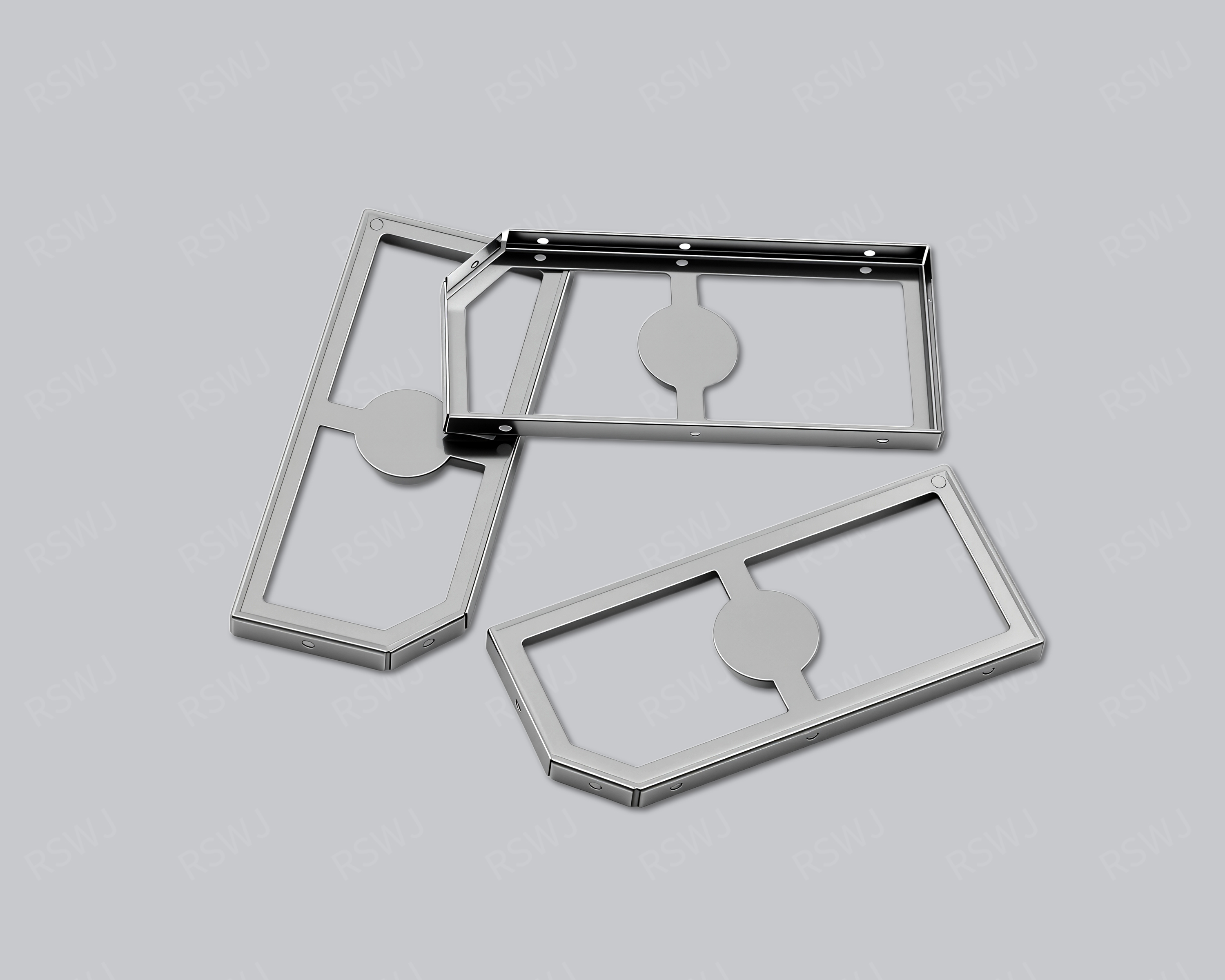
SMT Shielding Can
An SMT shielding structure connects local coverage with surface-mount placement and attachment.
Design & manufacturing details →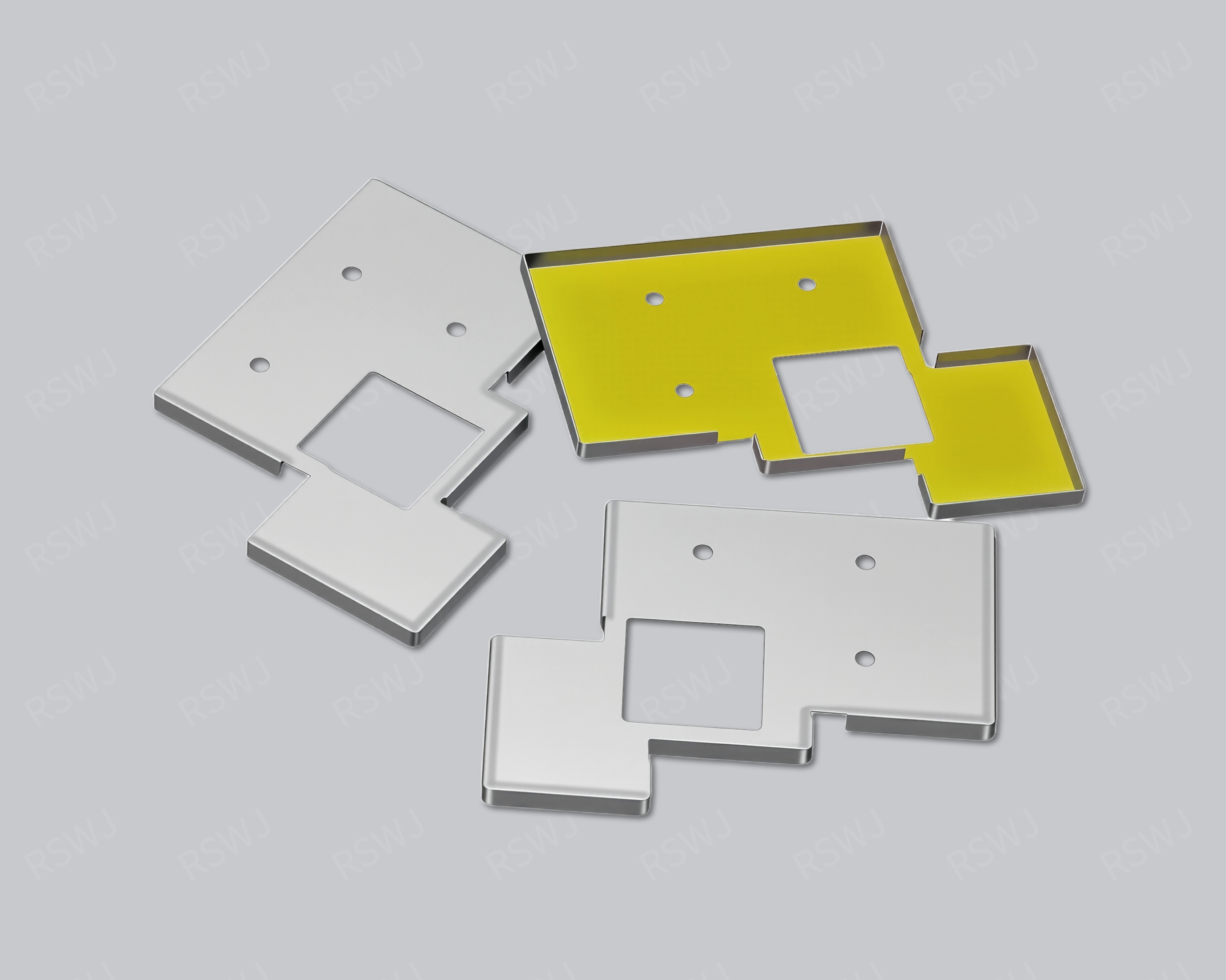
Stamped Shielding Can
A stamped shielding can converts sheet geometry into blanking and forming operations around finished-part datums.
Design & manufacturing details →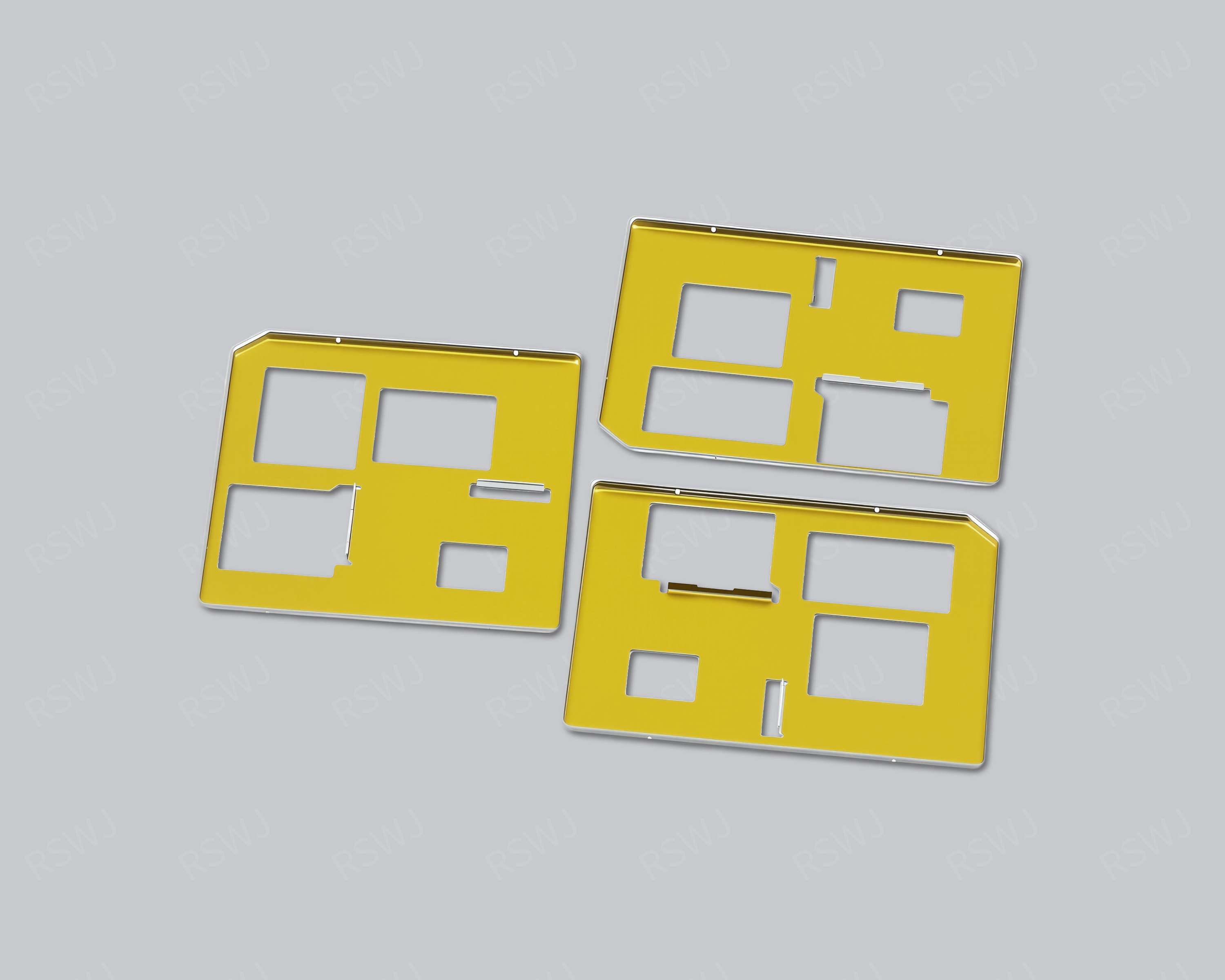
Deep-Drawn Shielding Can
A deep-drawn can develops a roof and sidewall contour through sheet forming, with trimming and interfaces defined afterward.
Design & manufacturing details →Discuss your Nickel-Plated Shielding Can project
Send the current drawing and mating conditions so we can review the structure, material, sample scope and required checks.
Send your project requirementsExplore manufacturing & finishes