
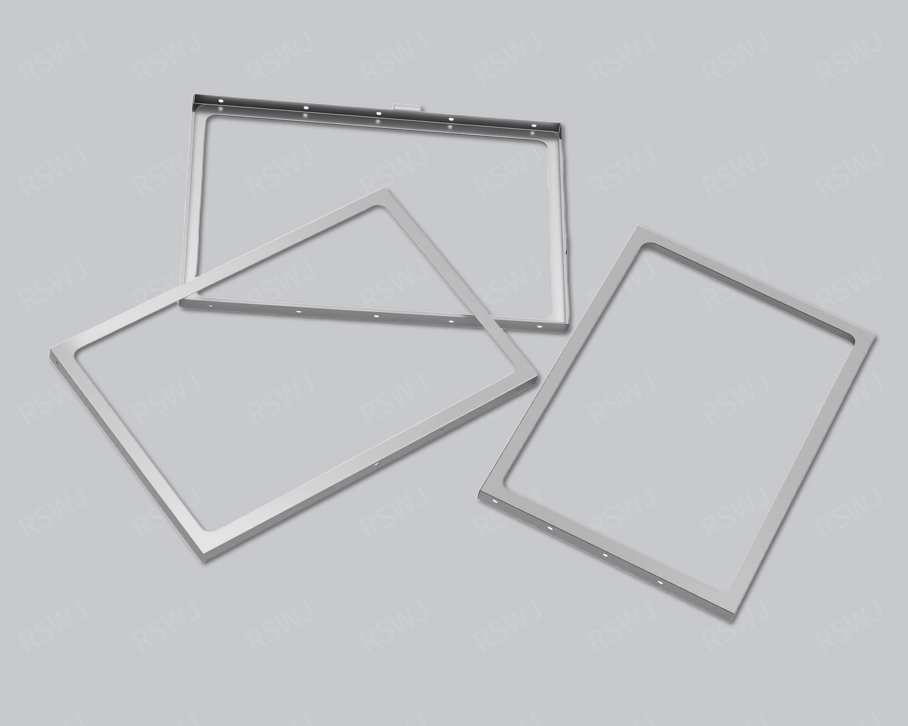
Reference photograph. Material, dimensions and mating requirements are defined in the agreed project drawings.
Local coverage within connected equipment
A communication circuit shield coordinates local coverage with actual signal ports, supply and host or equipment interfaces.
| Design focus | Signal regions, port exits, host assembly and connected-equipment configuration |
|---|---|
| Project task | Local coverage within connected equipment |
| Custom inputs | Current drawings, mating parts, material and final surface, quantity and acceptance requirements. |
Local coverage within connected equipment
Communication projects can contain RF, high-speed digital or other signal regions. Define which function is covered and how connectors or cables cross its boundary.
A communication-equipment shield is one boundary within a larger housing, wiring and port arrangement. Define the covered board region and relevant external paths. Check access and mounting in the finished equipment, not only on a module laid on a bench. Compare the customer’s relevant simultaneous functions with consistent cables and interfaces. This allows observations to be tied to a complete configuration and prevents an isolated shield fit result from becoming a claim for the whole equipment.
Engineering considerations for this project
Identify local coverage within the complete equipment
A communication-equipment shield is one physical boundary within an arrangement of boards, housing, wiring and external interfaces. Identify the electronic region selected for coverage and show its relationship with the other equipment parts. A cover can be mechanically correct for that local region without describing every connection through the complete enclosure. Separate the local metal task from the equipment boundary so engineering can identify which interfaces belong to the component drawing and which belong to a wider installation measure. This gives the manufacturer a concrete structure to review without assigning the behavior of unspecified connected equipment to a photographed metal reference.
Trace the relevant paths beyond the covered board, including the customer’s actual ports and connected wiring. Show where each path crosses the proposed metal and where it enters the larger housing or another assembly. A local opening and an external equipment port may serve the same connection but require different access and locating information. Label their purposes and the parts that control them. This helps avoid an enclosure proposal that appears complete in a board-level view while leaving an important installation operation or interface relationship unresolved in the equipment’s final connected arrangement.
Review access in the finished equipment condition
Examine the sequence used to install the shielded board and complete its connections inside the housing. Identify which neighboring boards, brackets or other customer-defined parts are already fitted, and show the operator or tool access available at that stage. A sample checked outside the equipment can establish component dimensions, but it cannot demonstrate every installed access requirement. Trial the relevant operations with the specified surrounding parts. Localize an obstruction or seating issue against the equipment references so a proposed change addresses the actual interaction rather than simply reducing the outside size of the cover.
If the project requires later service, distinguish that operation from the initial build. Identify whether the shield is opened in place, leaves with the board or remains fitted while another part is accessed. These strategies impose different requirements on retention, connection release and handling. Check the selected sequence in the finished equipment condition and observe the restored arrangement afterward. Keep the housing and connecting-part revisions with the sample record. This establishes a repeatable mechanical decision and makes clear why a cover removable from an isolated board may need a different access arrangement when installed among the equipment’s other assemblies.
Compare the customer’s relevant connected functions
For a functional comparison, retain the external connections and activity combinations associated with the customer’s concern. The equipment may behave differently in an isolated development setup and in the intended connected arrangement, so identify which setup each observation represents. Label a housing, port or wiring revision separately from a metal-cover change. This does not prevent testing combined design proposals; it keeps their scope interpretable. The customer can then decide which evidence supports the selected local shield and which evidence describes an additional equipment or interface measure that must be defined independently before procurement.
An inquiry should include the covered region, the equipment mounting and housing references, the relevant connection paths and the assembly or service sequence. State the required material and final surface with the selected drawing revision, and identify any partner information still under review. Include customer acceptance conditions without substituting a generic communication-equipment approval statement. These inputs support a controlled manufacturing discussion and establish which checks should be repeated when an external port, neighboring board or housing arrangement changes. They keep the metal component tied to its actual role within connected equipment rather than assuming that a local fit result establishes a whole-system performance value.
Boundary, clearance and mating design
Mark circuit partitions, interface exits and attachment references. Any shared cover or internal partition needs a relationship with the real module layout.
Translate the application into an actual circuit region. Mark the devices, interfaces and surrounding functions involved in the project concern. The equipment name can help organize discussion, but it does not provide hidden dimensions, compatibility or operating performance. Identify what must remain outside the metal boundary, such as a functional antenna, optical region or connection operation. The perimeter then follows a defined electronic and mechanical task rather than an arbitrary rectangle around the board.
Material and final surface definition
Select the material and final surface through forming, attachment, contact and the customer environment. The application label does not determine an alloy or coating for the reference. Specify grade, condition and thickness where required, with the final treatment separate. A working cover edge and a board joining region may need different checks. If a material alternative is evaluated, keep its changed conditions clear instead of treating it as an interchangeable color or marketing designation.
Forming and the installation sequence
Review board mounting, test access and finished-equipment installation. Cable connection and thermal parts can change the space available for cover operations.
Use the real mounting references and component envelopes to establish fit. Review the path used to place the shield, connect interfaces and fit the surrounding housing. The final position can clear a connector while the required insertion motion remains blocked. Mark intentional contacts separately from required gaps. When another part loads the roof, check the installed state rather than using an unloaded cover height as the full clearance decision.
A module boundary and an equipment boundary differ
Compare coverage through the actual signal region, connectors and paths into the next assembly. A module may fit on its own but acquire new thermal, cable or access constraints in the host. Identify which interfaces are fixed and which can move. Review the installed housing and customer port conditions. The broad communication name cannot supply a universal geometry, material choice or validated transmission result.
Part inspection and application evaluation
Use customer-defined port and operating configurations. Record the module, host and enclosure versions rather than treating an isolated idle module as the full integration case.
A drawing package for this custom part
| Input | What makes it usable |
|---|---|
| Coverage & interfaces | Signal regions, port exits, host assembly and connected-equipment configuration. Mark their relationship with the actual circuit or mating layout; identify fixed references and permitted changes. |
| Final part & datums | A dimensioned finished-part drawing and available 3D information. Identify functional dimensions, the installed condition and the measurement references used to accept them. |
| Material & surface | The specified grade, condition, thickness and final treatment. Show contact, joining and insulated regions separately; identify any alternative that needs evaluation. |
| Assembly & acceptance | Corresponding mating revisions and the installation or access sequence. Distinguish part inspection, matched fit and customer system checks with their agreed conditions. |
Questions for this design review
How is a communication sample kept tied to integration?
Record the module and host revisions, connectors, cable arrangement and relevant active ports. Trial installation and cover access in the actual enclosure. Separate those fit observations from customer system comparison. If a port or cable route changes, review the affected wall and opening even when the metal part is unchanged. This gives the local shielding task a defined boundary within the connected equipment.
Which drawings support the review of Communication Equipment Shielding Can?
Use the current layout and mating assembly to identify signal regions, port exits, host assembly and connected-equipment configuration. Mark the relationship that is already fixed and the specific feature being considered for change. A drawing of the cover alone may omit the condition that gives the reference its engineering purpose. Include the corresponding board or base and the intended operation so the proposed revision can be evaluated against a defined task rather than a similar-looking external shape.
In-House Tooling & Formed-Part Quality
Tooling development and forming quality
The manufacturing review for Communication Equipment Shielding Can connects how critical features are formed, how they are inspected and how they meet the mating assembly. Ruishuo links in-house die design and CAD/CAM simulation with stamping. Die-making output of more than 100 sets per month is a factory capability; the tool concept is reviewed for the actual project.
Ports and controlled assembly revisions
Review multi-interface modules with their connectors, cable exits and enclosure fixings. Give local openings, walls and attachment edges finished-part inspection datums. Tool-controlled dimensions need to relate to installation, connection and lid-access operations.
- Ports and coverage boundaries
- Express the interfaces and geometry in compatible structural and layout revisions. Identify opening purposes and functional contact surfaces.
- Fit after installation and connection
- Check the sample with matching interfaces, cables and mating parts. Review affected dimensions and tooling when the installation method or layout changes.
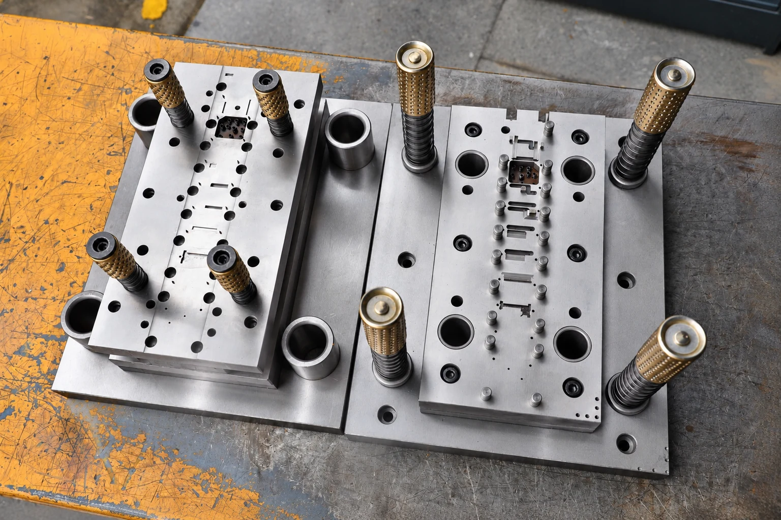
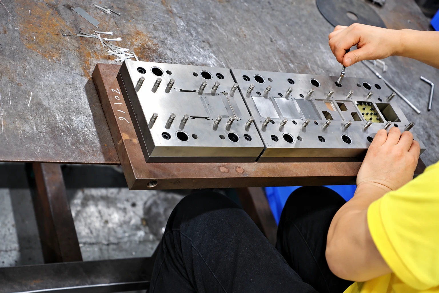
Paid samples include a full dimensional inspection report. Define drawing datums, acceptance criteria and corresponding mating parts so measurement and installed-fit checks can each answer the correct question. Confirm the charges, responsibilities and revision requirements for design changes, tooling work and later production stages within the project scope.
Paid samples and project planning
Samples are chargeable. Reference planning: standard samples 3–5 days; expedited sampling 48 hours; tooling and sample production 7–10 days. These are sample-stage arrangements, excluding mass-production delivery. The project plan is reviewed against the confirmed information, process and sample scope.
Related structures and project directions
Compare references through their coverage, installation and manufacturing tasks.
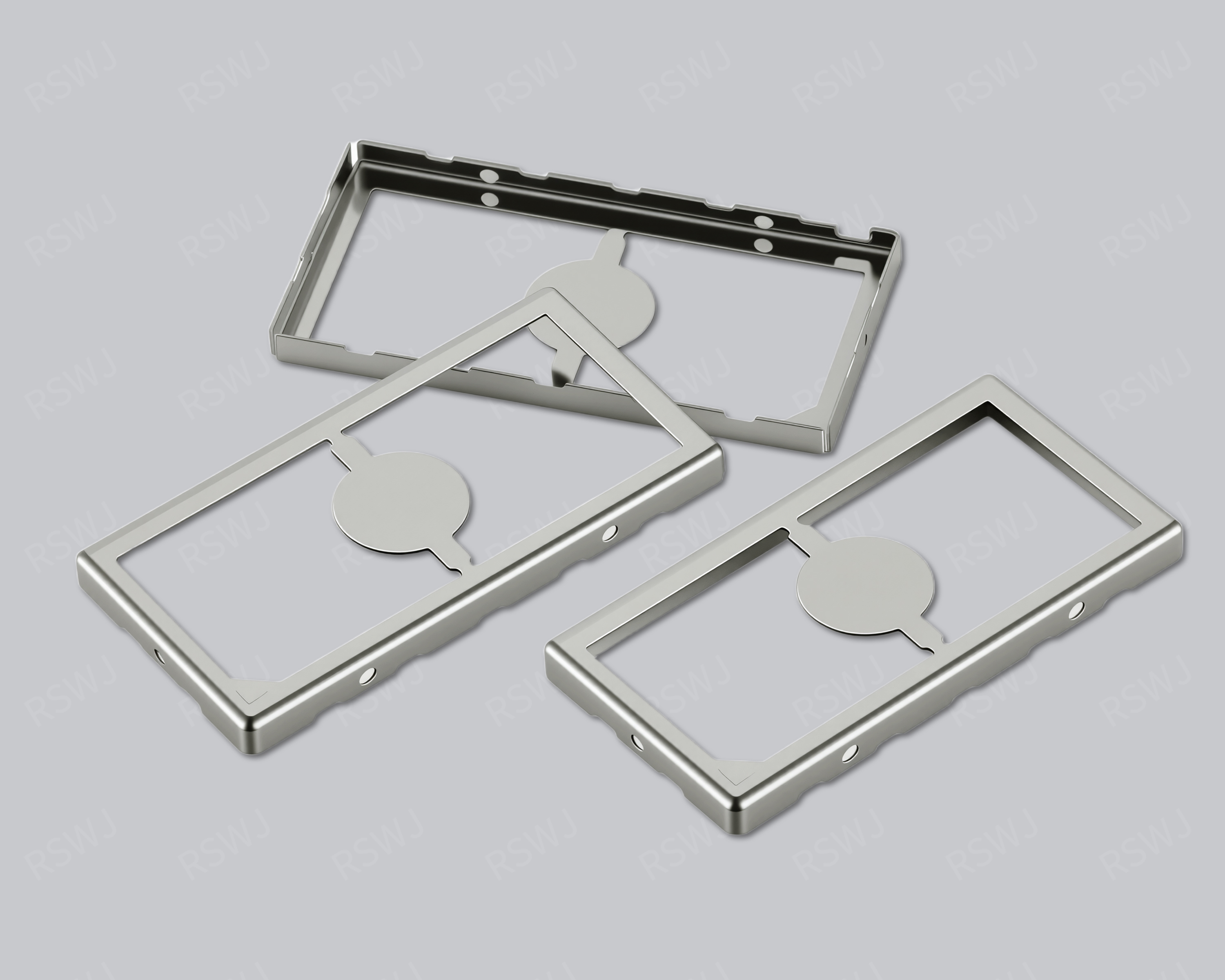
Communication Circuit Shielding Can
A communication circuit shield coordinates local coverage with actual signal ports, supply and host or equipment interfaces.
Design & manufacturing details →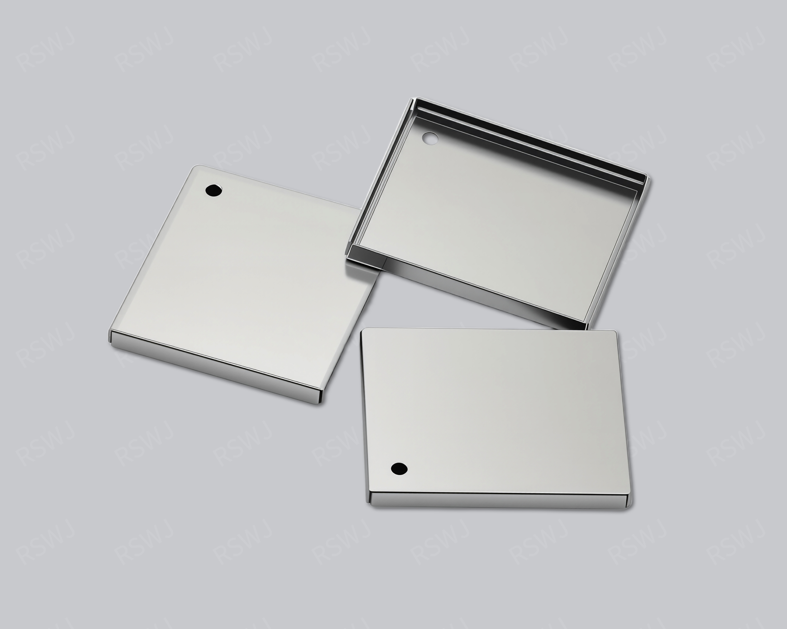
Communication Module Shielding Can
A communication circuit shield coordinates local coverage with actual signal ports, supply and host or equipment interfaces.
Design & manufacturing details →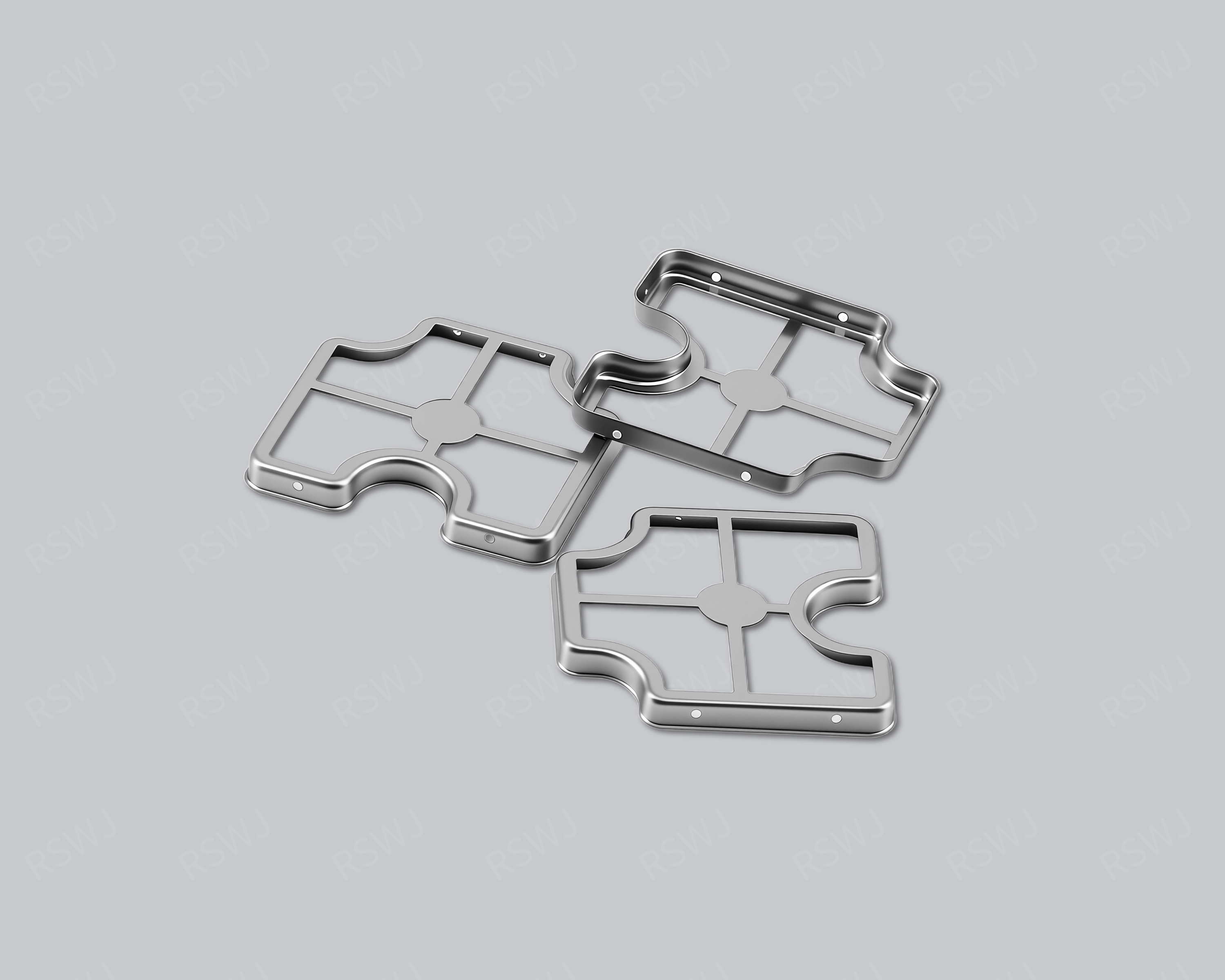
5G Circuit Shielding Can
A 5G shielding can is designed around a specified communication circuit region and its integration conditions.
Design & manufacturing details →Discuss your Communication Equipment Shielding Can project
Send the current drawing and mating conditions so we can review the structure, material, sample scope and required checks.
Send your project requirementsExplore electronic applications