
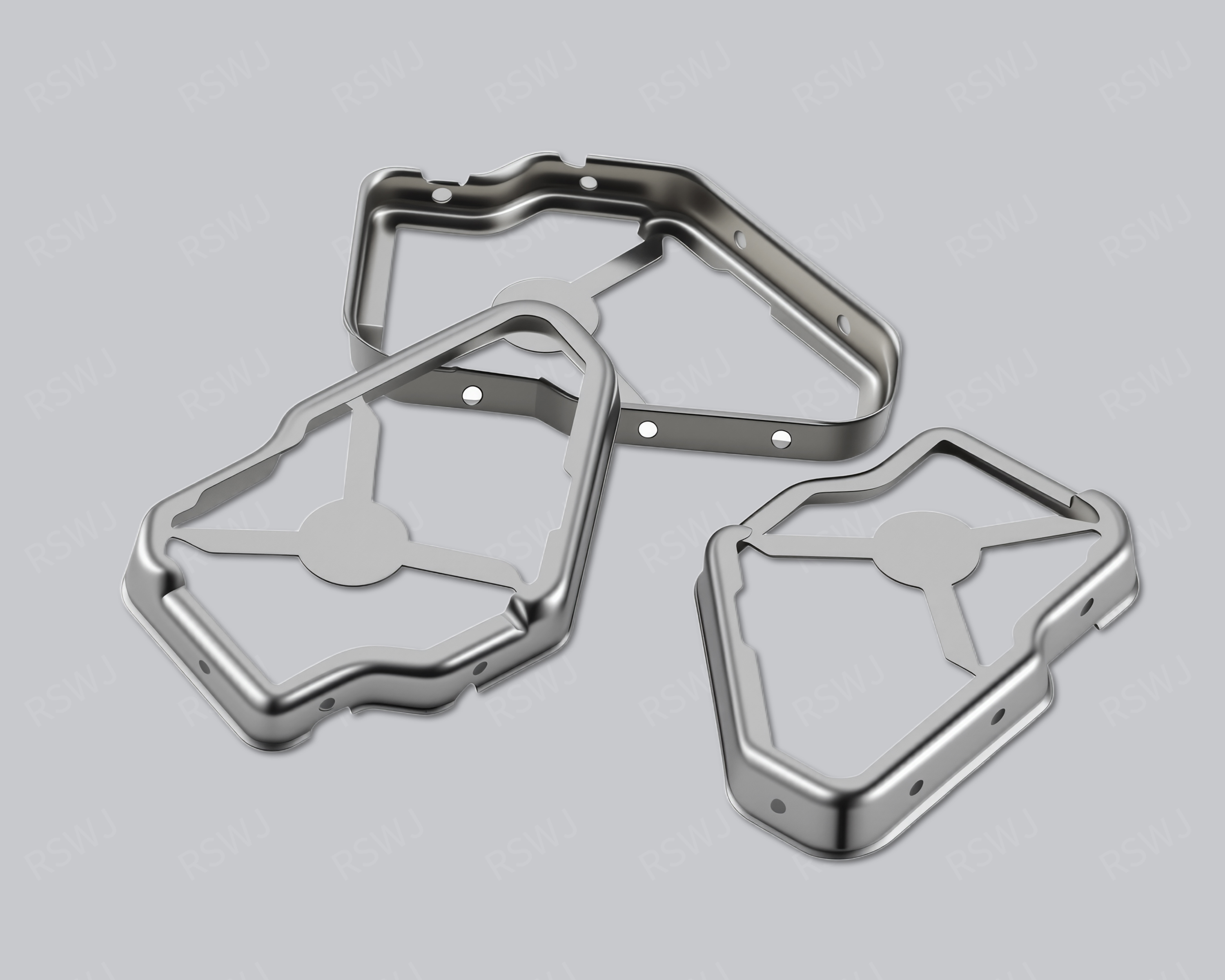
Reference photograph. Material, dimensions and mating requirements are defined in the agreed project drawings.
An exact copper-alloy designation matters
A copper-nickel alloy shield needs an exact material definition rather than appearance-based selection.
| Design focus | Alloy identity, allowed substitutions, mating geometry and surface version |
|---|---|
| Project task | An exact copper-alloy designation matters |
| Custom inputs | Current drawings, mating parts, material and final surface, quantity and acceptance requirements. |
An exact copper-alloy designation matters
Copper-nickel and copper-nickel-zinc descriptions are not automatically interchangeable. State grade and condition before comparing forming, joining and final contact arrangements.
Resolve the copper-nickel grade and supply condition before comparing this reference with nickel silver or another similar-looking material. Provide the final surface and permitted substitutions separately. Keep forming, mating and installation requirements tied to that material version. If an alternative is approved for evaluation, use the same comparison basis and inspect the affected features. This focuses procurement on a reproducible alloy definition rather than a color name or an assumed equivalent.
Engineering considerations for this project
Confirm the alloy identity before reviewing the metal shape
A copper-nickel alloy reference should begin with an exact material designation and the standard or supplier information that defines it. Broad copper-alloy names are not interchangeable descriptions of composition or supply condition. Ask the customer to identify the intended alloy and distinguish that choice from a surface treatment applied later. If the project is considering alternatives, record them as separate proposals rather than treating the original label as permission to substitute any similar-looking material. This gives the manufacturer a clear starting point for reviewing the formed geometry and prevents a procurement decision from resting on an ambiguous trade description.
State the supplied condition and the functions expected of the formed part. The same named family can enter a project with different forming, contact or retention requirements, so material identity should remain connected to the actual cover or component design. Locate the bends, working edges and mating regions that matter to the application. The manufacturer can assess those features against the confirmed material input without inventing a composition, hardness or universal forming value. If the name in an old reference is uncertain, clarify it before assigning the material to a new drawing or comparing a sample from another supplier.
Separate alloy selection from joining and final-surface requirements
The drawing should identify how the metal is attached and which regions participate in the project’s intended conductive contact. State any customer-defined joining conditions and the final surface required at those regions. A chosen alloy name does not by itself establish a joining method or the condition of a treated surface. If the component receives a later process, describe its scope independently from the substrate. This makes it possible to review the formed part, the processed part and the installed interface as related but distinct conditions instead of accepting them through one general material description.
Use the relevant mating parts for sample assessment, examining the actual working edges and closure or attachment operation. A surface selected for appearance elsewhere on the component should not silently define a functional contact region. Likewise, a measurement taken before a later process may not represent the final mating condition. Identify which state governs each check and retain the material and surface versions together in the sample record. This gives engineering a practical way to distinguish a geometry issue from a material-input or processing issue when a cover behaves differently from the reference during installation.
Make an alternative alloy comparison traceable
When considering an alternative, state the reason for the change and identify the functions that need to remain comparable. A proposal motivated by supply availability may still require a forming review and a check of the agreed attachment or contact surfaces. Keep the geometry and mating arrangement recognizable so the customer can assess the alternative without confusing it with a simultaneous design revision. If the proposed material requires an adjusted contour or operation sequence, record that change separately. The comparison then has an identifiable scope rather than being reduced to whether two samples share a similar color or outside outline.
For an order or sample request, provide the exact alloy designation, supply condition, required final surface and drawing revision. Identify any permitted alternatives and the approval process for using them. Include the mating information and inspections associated with the part’s actual role, whether it forms an enclosure, a closure or another specified interface. These inputs support a controlled discussion of the copper-nickel alloy reference without assigning an unprovided performance value or process capability to it. They also make later material or surface changes reviewable against the original functions and acceptance conditions instead of an imprecise family name.
Boundary, clearance and mating design
Coordinate sidewalls and mating edges with the selected alloy. Define which geometric and assembly conditions stay fixed when evaluating a substitute.
A material comparison is most useful when the geometry and installed interfaces are identified. Mark where the shield lands, where it closes and where signals or connectors cross the boundary. The intended circuit region and operating context remain important even when the search began with an alloy name. A different material is not a substitute for an undefined attachment or opening. Keep those relationships fixed, or explicitly identify them as changes, when evaluating alternatives.
Material and final surface definition
Build the material definition from the applicable grade or standard, supply condition, thickness and final surface. State which requirements are mandatory and which alternatives may be reviewed. If documentation is needed, identify its scope with the project rather than assuming a product photograph supplies it. This separates identity from performance: the material record establishes what was used, while the agreed part and application checks establish the relevant condition of the sample.
Forming and the installation sequence
Identify permitted substitutions and the checks they trigger. A sample approved in one material version remains identifiable when another version is discussed.
Review the actual formed features with the material condition. Bends, small corners, cut edges and working retention areas pose different questions from a flat sheet. Specify functional dimensions on the finished component using meaningful datums. If later processing changes a mating surface, inspect the final state. The manufacturing route should be reviewed with the whole drawing package instead of selected from the alloy name without its geometry and installation requirements.
Keep copper-alloy terminology consistent
Resolve the alloy designation used by engineering and purchasing, particularly when similar translated material names appear in source documents. Identify a copper-nickel requirement separately from a copper-nickel-zinc option. Compare material versions under the same shape and installation basis, with changed forming or finish inputs recorded. A controlled comparison helps assess the actual mating consequences instead of approving a substitution because both samples appear pale or copper-alloy based.
Part inspection and application evaluation
Check material documents, formed geometry and installed closure. Functional comparisons retain the same attachment and operating arrangement.
A drawing package for this custom part
| Input | What makes it usable |
|---|---|
| Coverage & interfaces | Alloy identity, allowed substitutions, mating geometry and surface version. Mark their relationship with the actual circuit or mating layout; identify fixed references and permitted changes. |
| Final part & datums | A dimensioned finished-part drawing and available 3D information. Identify functional dimensions, the installed condition and the measurement references used to accept them. |
| Material & surface | The specified grade, condition, thickness and final treatment. Show contact, joining and insulated regions separately; identify any alternative that needs evaluation. |
| Assembly & acceptance | Corresponding mating revisions and the installation or access sequence. Distinguish part inspection, matched fit and customer system checks with their agreed conditions. |
Questions for this design review
How should allowable alternatives be documented?
List the exact material designations, supply conditions and final surfaces that may be evaluated, then identify the checks each change triggers. Keep drawing and sample versions distinguishable. If the customer needs a fixed alloy, do not treat an alternative as accepted merely because an initial fit is possible. Material identity, dimensional fit and the relevant project verification provide different parts of the acceptance record.
Which drawings support the review of Copper-Nickel Alloy Shielding Can?
Use the current layout and mating assembly to identify alloy identity, allowed substitutions, mating geometry and surface version. Mark the relationship that is already fixed and the specific feature being considered for change. A drawing of the cover alone may omit the condition that gives the reference its engineering purpose. Include the corresponding board or base and the intended operation so the proposed revision can be evaluated against a defined task rather than a similar-looking external shape.
In-House Tooling & Formed-Part Quality
Tooling development and forming quality
The manufacturing review for Copper-Nickel Alloy Shielding Can connects how critical features are formed, how they are inspected and how they meet the mating assembly. Ruishuo links in-house die design and CAD/CAM simulation with stamping. Die-making output of more than 100 sets per month is a factory capability; the tool concept is reviewed for the actual project.
Material condition and formed-part behavior
Specify material grade, thickness and supply condition with the tooling inputs. A material change can affect bending, springback and contact features, so matching the old outline is only part of the review. Define the final attachment, opening and engagement requirements.
- Complete material inputs
- Record the specified grade, thickness, condition and finish. For substitutions, agree the acceptable range and affected validation items.
- Checks against the mating assembly
- Keep the material and drawing revision with the sample report. Check the controlled dimensions, then verify the actual attachment and closure.
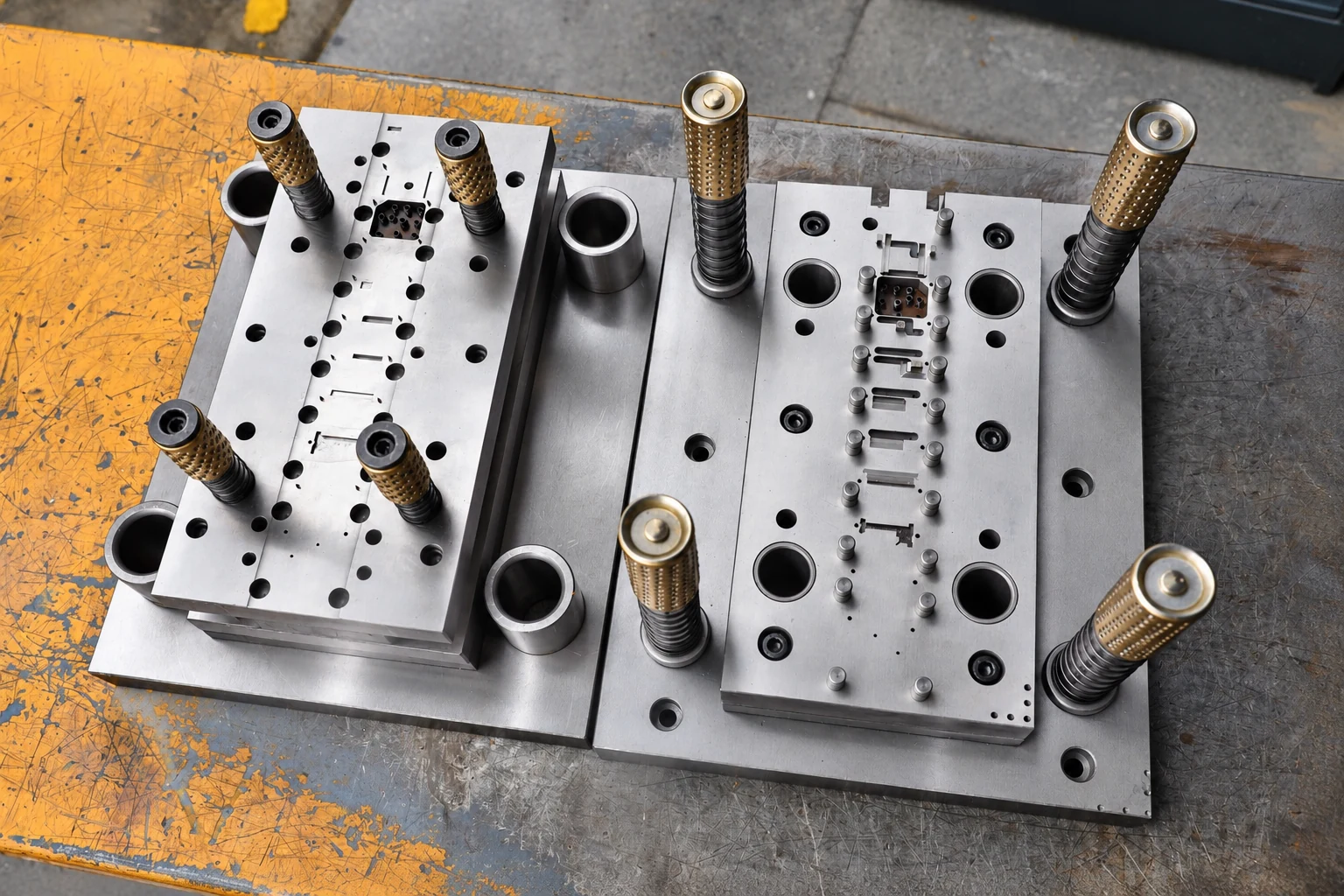
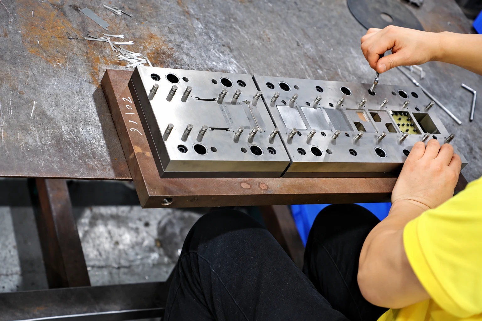
Paid samples include a full dimensional inspection report. Define drawing datums, acceptance criteria and corresponding mating parts so measurement and installed-fit checks can each answer the correct question. Confirm the charges, responsibilities and revision requirements for design changes, tooling work and later production stages within the project scope.
Paid samples and project planning
Samples are chargeable. Reference planning: standard samples 3–5 days; expedited sampling 48 hours; tooling and sample production 7–10 days. These are sample-stage arrangements, excluding mass-production delivery. The project plan is reviewed against the confirmed information, process and sample scope.
Related structures and project directions
Compare references through their coverage, installation and manufacturing tasks.
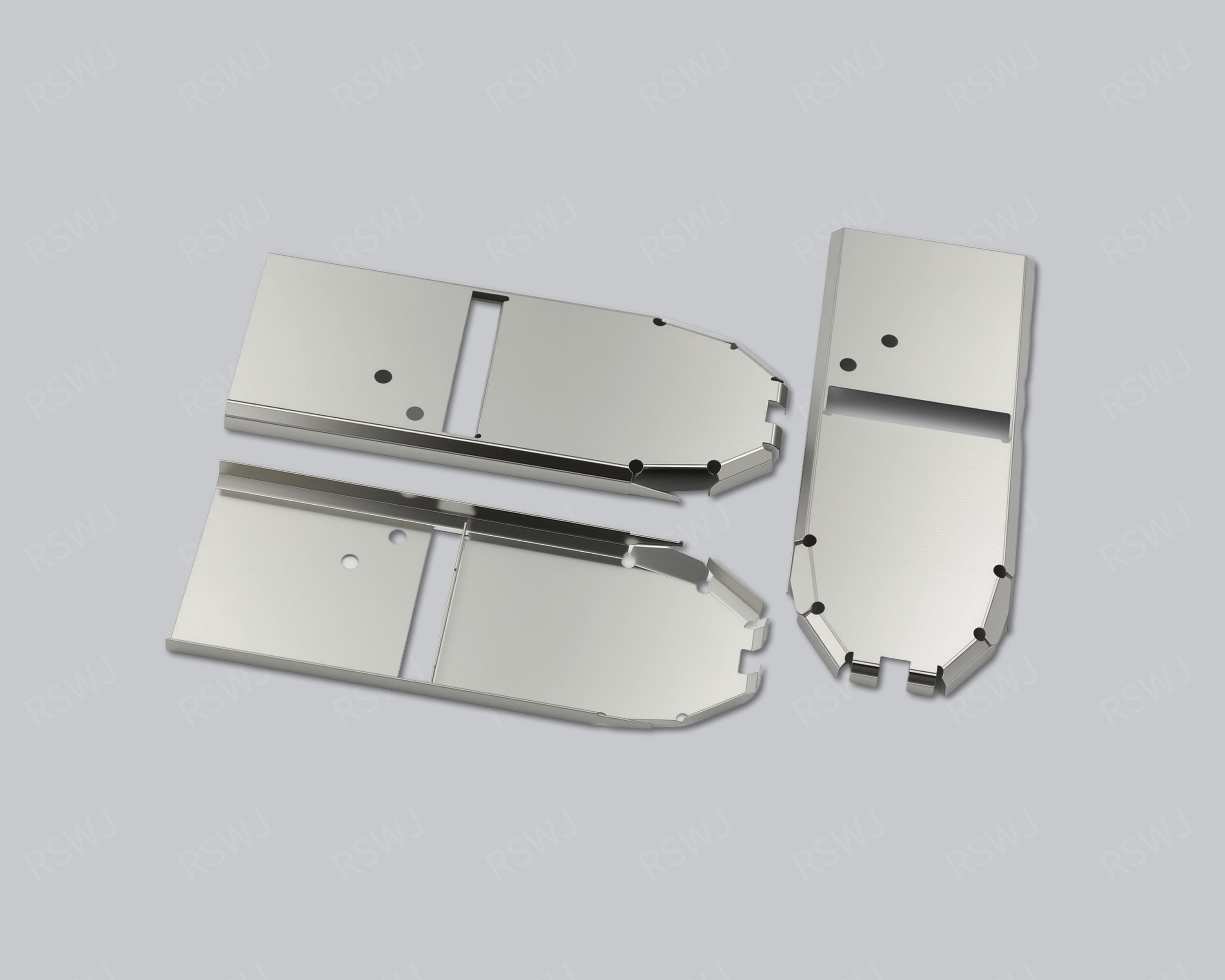
301 Stainless Steel Shielding Can
A 301 stainless steel shielding can starts with a specified alloy grade and a separately defined material state.
Design & manufacturing details →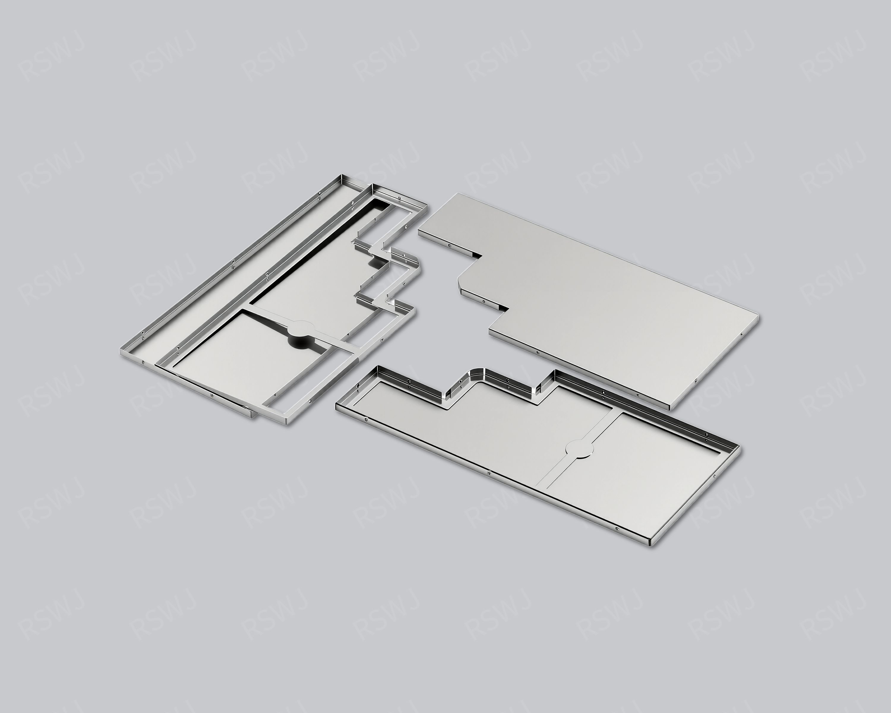
Stainless Steel Shielding Can
A stainless steel shielding can requires a specific grade, supply condition and joining arrangement.
Design & manufacturing details →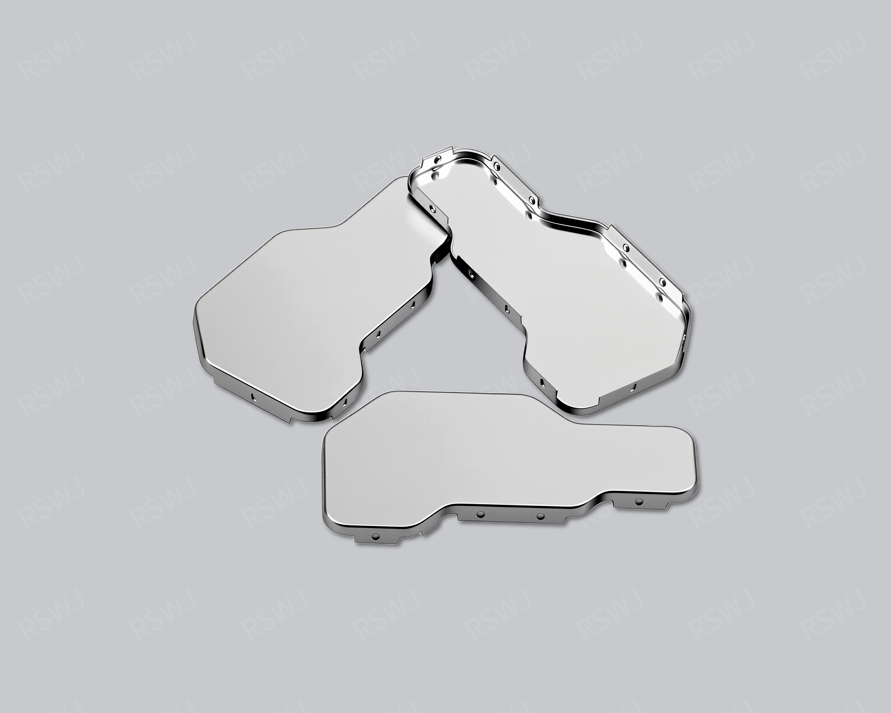
Permalloy Shielding Cover
A permalloy cover addresses a defined magnetic-field problem with an agreed alloy and treatment condition.
Design & manufacturing details →Discuss your Copper-Nickel Alloy Shielding Can project
Send the current drawing and mating conditions so we can review the structure, material, sample scope and required checks.
Send your project requirementsExplore shield materials