
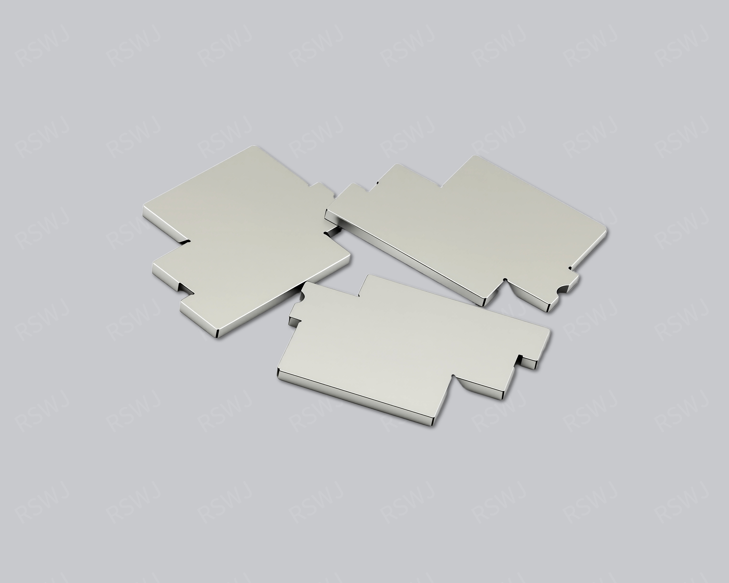
Reference photograph. Material, dimensions and mating requirements are defined in the agreed project drawings.
Define the lid with its corresponding base
A shielding lid closes the upper side of a frame or base and is defined with that mating structure.
| Design focus | Base revision, lid perimeter, top-plane contact and removal access |
|---|---|
| Project task | Define the lid with its corresponding base |
| Custom inputs | Current drawings, mating parts, material and final surface, quantity and acceptance requirements. |
Define the lid with its corresponding base
The lid interface connects the roof and perimeter wall. Outline dimensions alone cannot define overlap, corner gaps, retention or the installed cover posture.
A separately supplied EMI lid should have a clear corresponding frame or base. Provide that mating revision and the seated relationship, including contact edge, retention and removal direction. If the lid includes top contact or an opening, assess it after closure rather than as an isolated sheet shape. Purchasing can then distinguish a replacement lid from a newly matched assembly. Avoid accepting a cover solely because its outside dimensions resemble an earlier part.
Engineering considerations for this project
Specify the lid from its corresponding base
An EMI lid needs the frame, base or upper opening it is intended to close. Provide that counterpart revision and show the features that locate the lid, define its seat and retain it in the working position. The roof outline alone does not describe those relationships. A separately purchased cover can therefore have a precise supply requirement even where the base is customer-owned. The drawing should distinguish its free shape from the installed relationship, giving the manufacturer enough information to review forming and final fit without redesigning an unspecified surrounding assembly. The counterpart drawing should identify any fixed feature that the new lid must retain, with local assembly views available where the perimeter relationship cannot be understood from outside dimensions alone.
Local perimeter views can clarify corner overlap and entry features. Identify where the cover approaches the base and which surfaces establish its final position. If an opening or top contact is present, relate it to the seated lid rather than only the flat roof. A feature added for one upper interface may affect a perimeter region used for closure. Reviewing those relationships together lets the project discuss a targeted cover revision and keeps a local requirement from being assessed independently of the mating edge that actually locates the supplied part.
Choose a usable installation and removal operation
A lid that fits a loose base may encounter another operation in the completed product. Include the enclosure, nearby connectors and upper parts that constrain pressing, gripping or extraction. State the intended direction and permitted handling regions so the sample can reproduce that operation. If the cover is only installed once, distinguish that task from later service access. If repeated opening is part of the project, show the prerequisites and the counterpart condition that remains after removal. This gives the structural review a practical reason for selecting the relevant engagement and access features.
Trial closure with the matching base in its actual installed condition. Locate any seating concern by the relevant perimeter region and identify whether it appears during entry, at the stop or after another upper part is fitted. If a thermal interface or other contact loads the roof, retain that condition with the observation. These details help engineering distinguish a lid-forming issue from a base position or upper-assembly relationship. They also avoid using overall cover dimensions as the only criterion when the actual project depends on corners, engagement locations and access within the assembled product.
Define replacement compatibility through checked combinations
A replacement lid request should identify the base or frame versions it is intended to serve. State whether the approval covers one corresponding combination or a wider set of checked counterparts. The sample assessment can then use the relevant installed references and operation. If a base version differs, locate its changed engagement, seat or upper opening before assuming compatibility. This makes a component-only purchase understandable and gives purchasing an acceptance scope tied to the working assembly rather than an exterior shape that happens to resemble another cover.
When the lid changes, identify the affected mating or top interface and retain the unchanged base where appropriate. When the base changes, review the corresponding cover relationship even if the lid drawing is preserved. Record the checked component versions and the installed condition in the approval package. A later request can reproduce that combination or state a deliberate new compatibility task. This controlled relationship supports separate lid supply, spare components and new cover development without implying that every similarly named EMI lid is interchangeable with an unspecified frame, housing or previously approved assembly.
Boundary, clearance and mating design
Coordinate the top plane, retaining features and removal access. Review openings or thermal contact against the seated cover and its edge interfaces.
A frame, lid or clip must be located within the complete shielding assembly. Identify its mating object and the part of the boundary it establishes. An open frame needs an upper closure, a lid needs a base and a clip needs the edge or component it retains. The standalone outline is therefore only one part of the definition. Show the working position and the interfaces that remain dependent on other components before discussing supply or inspection.
Material and final surface definition
Define the material and condition for each component according to its role. A fixed frame, a deflecting clip and a roofed lid can require different working checks even when the project uses one broad alloy family. Specify final surfaces at joining and mating regions separately from non-contact appearance. The component name does not establish its grade, thickness or process state, so those requirements remain part of the drawing and material definition.
Forming and the installation sequence
Fit the lid after circuit and frame inspection. Follow the intended insertion or pressing direction and check access with surrounding parts installed.
Use the actual mating relationship to select datums and critical dimensions. A cover edge can be checked against a frame, while a frame landing is checked against the board. A clip’s free-state shape and working position need corresponding references. Specify the installation direction and any intended movement, with an inspection method that can reach the real feature. Individually accepted components still require a defined assembly check where the project depends on their combined fit.
A roof feature should be evaluated when seated
Compare lids through the mating base, not as independent outlines. A roof opening, thermal contact or added form can change the way the cover sits and is handled. Review those features with corners and retaining regions, then trial the actual installation and removal direction. A lid supplied as a replacement needs an identified compatible base and a corresponding fit check; its standalone dimensions are only part of that definition.
Part inspection and application evaluation
Assess seating, edge gaps and reinstallation. Thermally loaded covers need checks with the actual interface, not an unloaded height measurement alone.
A drawing package for this custom part
| Input | What makes it usable |
|---|---|
| Coverage & interfaces | Base revision, lid perimeter, top-plane contact and removal access. Mark their relationship with the actual circuit or mating layout; identify fixed references and permitted changes. |
| Final part & datums | A dimensioned finished-part drawing and available 3D information. Identify functional dimensions, the installed condition and the measurement references used to accept them. |
| Material & surface | The specified grade, condition, thickness and final treatment. Show contact, joining and insulated regions separately; identify any alternative that needs evaluation. |
| Assembly & acceptance | Corresponding mating revisions and the installation or access sequence. Distinguish part inspection, matched fit and customer system checks with their agreed conditions. |
Questions for this design review
How do top contacts affect lid acceptance?
Inspect the lid after the intended thermal or mechanical part is fitted. Identify the contact location and any load transferred through the roof, then check the perimeter and internal clearance. Keep the free-state measurements as a separate record. If service removes the upper contact first, use that sequence for refitting. This lets the project distinguish a roof-loading concern from a mismatch in the lid and base geometry.
Which drawings support the review of EMI Shielding Lid?
Use the current layout and mating assembly to identify base revision, lid perimeter, top-plane contact and removal access. Mark the relationship that is already fixed and the specific feature being considered for change. A drawing of the cover alone may omit the condition that gives the reference its engineering purpose. Include the corresponding board or base and the intended operation so the proposed revision can be evaluated against a defined task rather than a similar-looking external shape.
In-House Tooling & Formed-Part Quality
Tooling development and forming quality
The manufacturing review for EMI Shielding Lid connects how critical features are formed, how they are inspected and how they meet the mating assembly. Ruishuo links in-house die design and CAD/CAM simulation with stamping. Die-making output of more than 100 sets per month is a factory capability; the tool concept is reviewed for the actual project.
Cover geometry in the closed assembly
Define the cover outline, walls and engagement features with the mating frame, base or enclosure. Formed flatness, edge height and location affect the closed assembly. If the roof also meets a thermal interface or loading feature, include those conditions in the fit review.
- Inspection with the mating part
- Distinguish free-state and installed requirements. Check location, wall overlap, closed gaps and the actual contact regions.
- Access and reinstallation
- Specify handling positions and tool entry. Use the matching base to assess installation, removal and the refitted condition.
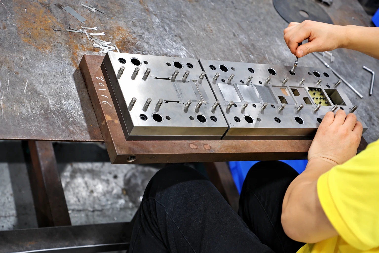
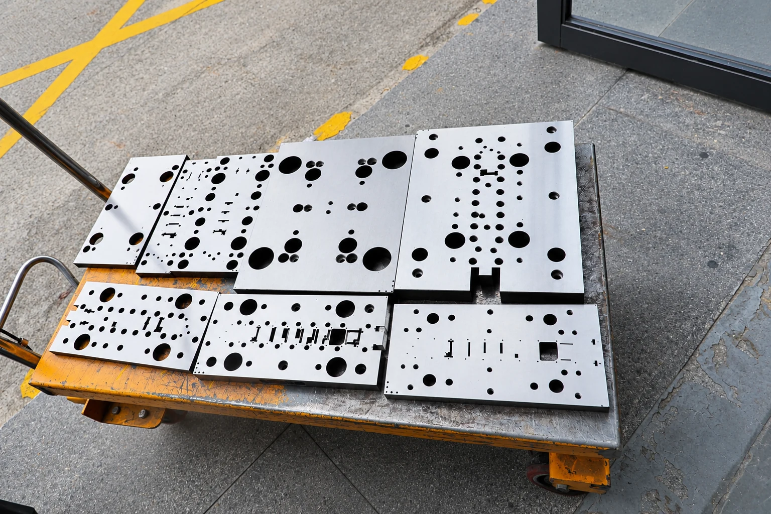
Paid samples include a full dimensional inspection report. Define drawing datums, acceptance criteria and corresponding mating parts so measurement and installed-fit checks can each answer the correct question. Confirm the charges, responsibilities and revision requirements for design changes, tooling work and later production stages within the project scope.
Paid samples and project planning
Samples are chargeable. Reference planning: standard samples 3–5 days; expedited sampling 48 hours; tooling and sample production 7–10 days. These are sample-stage arrangements, excluding mass-production delivery. The project plan is reviewed against the confirmed information, process and sample scope.
Related structures and project directions
Compare references through their coverage, installation and manufacturing tasks.
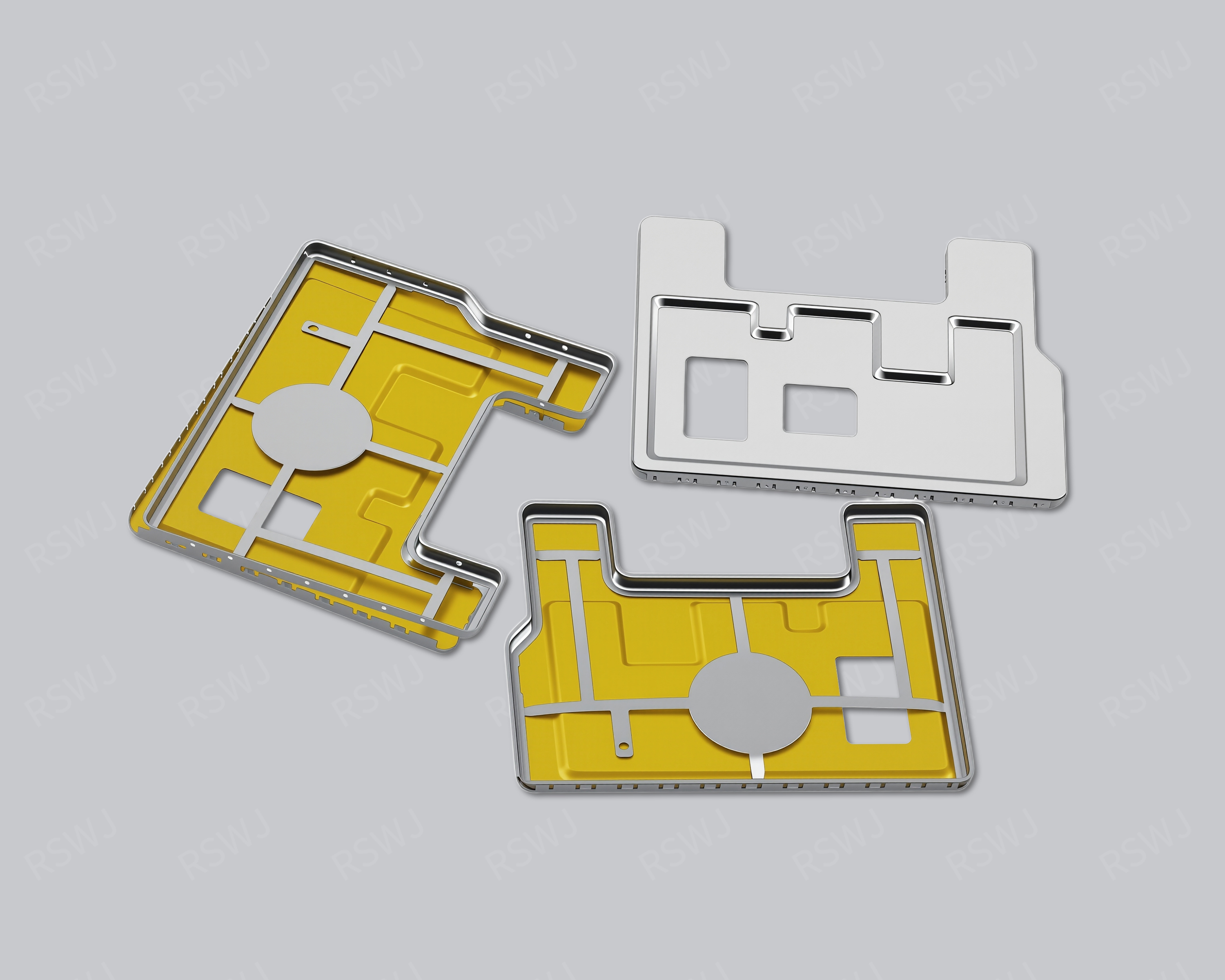
EMI Shielding Frame
A shielding frame connects a PCB attachment perimeter with the mating edge of a lid or other closure.
Design & manufacturing details →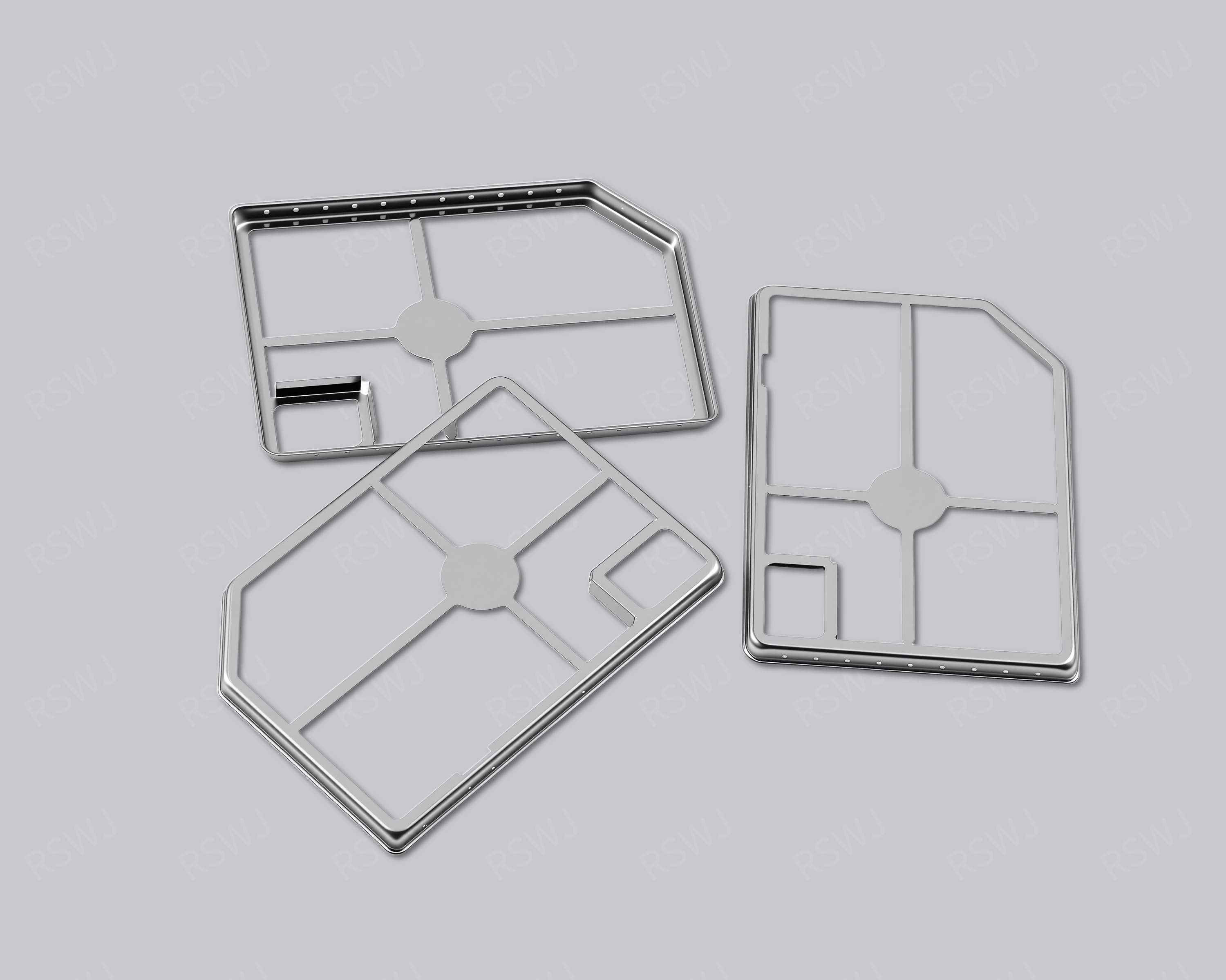
SMT Shielding Frame
An SMT shielding structure connects local coverage with surface-mount placement and attachment.
Design & manufacturing details →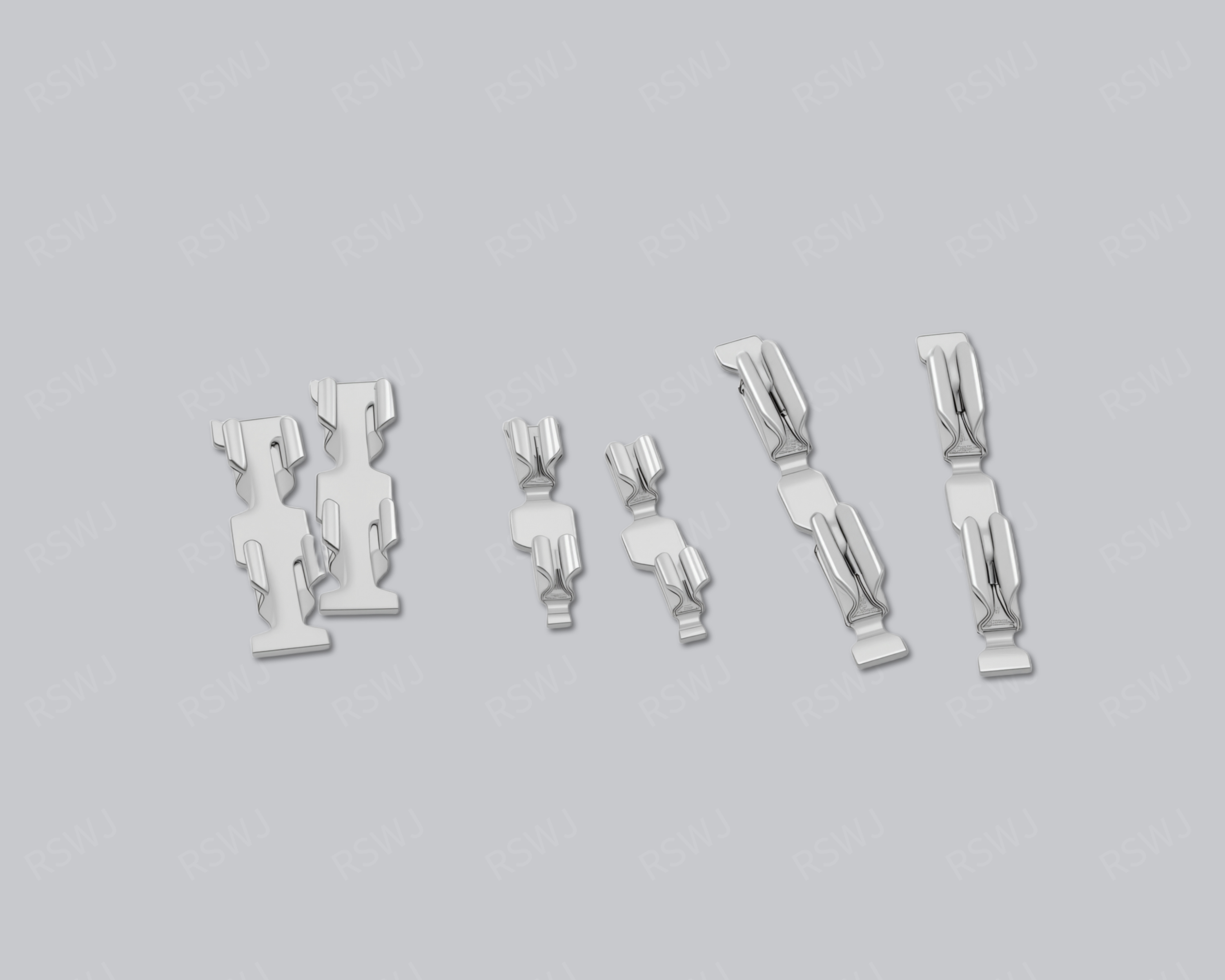
Shielding Clip
A shielding clip provides a local retaining or contact interface in a board-level assembly.
Design & manufacturing details →Discuss your EMI Shielding Lid project
Send the current drawing and mating conditions so we can review the structure, material, sample scope and required checks.
Send your project requirementsExplore frames, lids & clips