
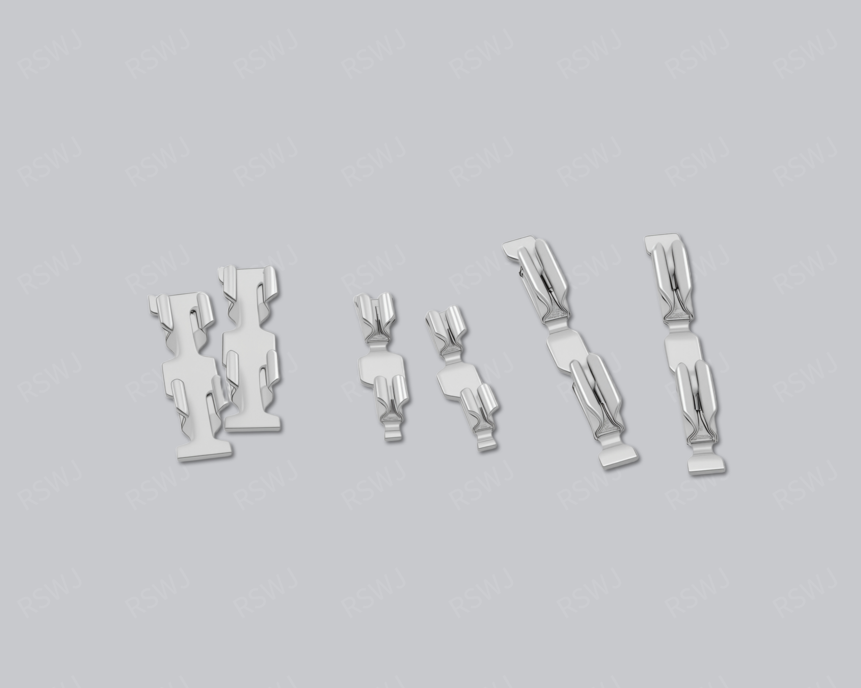
Reference photograph. Material, dimensions and mating requirements are defined in the agreed project drawings.
Define the clip in its working position
A shielding clip provides a local retaining or contact interface in a board-level assembly.
| Design focus | Mating thickness, insertion depth, working travel and clip locations |
|---|---|
| Project task | Define the clip in its working position |
| Custom inputs | Current drawings, mating parts, material and final surface, quantity and acceptance requirements. |
Define the clip in its working position
The clip is evaluated in its working position against the inserted edge. Several clips can hold a can while the rest of the boundary remains dependent on the can geometry.
Provide the inserted object, intended insertion depth and the clip’s working motion. An unloaded clip drawing should be linked to its installed position so inspection can assess both conditions appropriately. For several clips, review their collective effect on the shield edge and seated posture. State any force or repeated-operation requirement with a method and matching component. This distinguishes a functional clip specification from an outline that happens to resemble an existing part.
Engineering considerations for this project
Define the clip against the edge it retains
A shielding clip needs the actual mating object to establish its working role. Identify the inserted edge, its material and final surface, and the intended position after installation. The loose clip shape is not the whole assembly. A working deflection, insertion depth or stop can connect the geometry with how the can is retained or contacted. Mark those relationships explicitly so the sample can be assessed through a defined partner rather than through resemblance to an existing small component.
Compare a clip arrangement with a frame or direct attachment through the can outline and the intended access task. Clips can provide local interfaces while other parts of the perimeter retain separate requirements. Identify how the complete can is supported and positioned, including regions between clips. More local retaining points are not automatically the answer to a seating concern. The relevant question is how the actual clip locations and can edge establish the installed structure.
Use free and working states as separate inspection objects
Identify which dimensions describe the unassembled clip and which observations describe its installed condition. A feature intended to move should be checked with the specified mating object and insertion method. Choose datums and fixtures appropriate to those tasks, recording the partner version. This avoids treating working movement as an unexplained dimensional deviation or assuming that a correct loose shape establishes the complete holding and contact relationship.
Review material condition and functional surfaces alongside that movement. A formed bend, contact location and externally handled edge can need different acceptance observations. If a material or finish alternative is proposed, identify which working features are affected. Inspect the final delivered state with the same mating basis. The clip name does not provide a force, working travel or endurance rating; quantitative requirements need the customer’s defined partner, method and acceptance condition.
Trial the clip group and the installation operation
Use the planned clip positions and actual can edge to check the complete assembly. Record insertion direction, the support provided by neighboring clips and any region that lifts or rocks. A local clip trial can establish one interface without showing every combined position. If a concern appears only when the complete can is installed, inspect location and edge geometry as well as the clip itself. This gives a revision a clear assembly target.
Check tool and replacement access with the enclosure and adjacent parts present. Trial the intended removal and reinstallation motion rather than relying on an improvised route. Inspect the restored can position and designated contacts. If the project evaluates retention or repeated operation, keep that record separate from bare-part dimensions. Customer system evaluation uses the completed boundary and corresponding configuration. A local clip result should not be expanded into a result for every remaining interface.
Specify component supply through the mating scope
Provide the clip drawing, mating edge or component, installed locations and operation method together. State whether the request covers clips alone or a coordinated can assembly. Identify material, final surface and the checks required for sample acceptance. This allows manufacture of a reproducible local interface instead of treating a small reference photo as a fixed stock specification with universal compatibility.
When the can edge, clip position or insertion method changes, review the working relationship and recheck the assembled group. Keep accepted partner revisions in the repeat-order package. A replacement clip should be assessed through the same defined scope. This makes procurement and engineering decisions concrete while leaving unprovided holding-force, lifecycle and system-performance claims outside the component definition. Identify the can edge and installed clip locations together when approving the set. A change to edge thickness, surface or seating posture can alter the working relationship without changing the loose clip drawing. Retaining that partner definition allows a replacement or repeat clip to be assessed through the actual local interface rather than appearance.
Boundary, clearance and mating design
Define mating thickness, insertion depth and the working stop. For multiple clips, check their locations against the actual shield edge and installed posture.
A frame, lid or clip must be located within the complete shielding assembly. Identify its mating object and the part of the boundary it establishes. An open frame needs an upper closure, a lid needs a base and a clip needs the edge or component it retains. The standalone outline is therefore only one part of the definition. Show the working position and the interfaces that remain dependent on other components before discussing supply or inspection.
Material and final surface definition
Define the material and condition for each component according to its role. A fixed frame, a deflecting clip and a roofed lid can require different working checks even when the project uses one broad alloy family. Specify final surfaces at joining and mating regions separately from non-contact appearance. The component name does not establish its grade, thickness or process state, so those requirements remain part of the drawing and material definition.
Forming and the installation sequence
Use a controlled installation motion within the intended deflection. Surface matching and access for replacement belong in the material and assembly review.
Use the actual mating relationship to select datums and critical dimensions. A cover edge can be checked against a frame, while a frame landing is checked against the board. A clip’s free-state shape and working position need corresponding references. Specify the installation direction and any intended movement, with an inspection method that can reach the real feature. Individually accepted components still require a defined assembly check where the project depends on their combined fit.
A local contact within a larger assembly
Compare a clip arrangement with a frame or direct attachment using the actual can edge and installation task. Clip positions, mating thickness and working movement must be coordinated; adding clips does not by itself define the remaining perimeter. Check clearance for placement and replacement, including tools. The material and surface of both mating parts are relevant, while the required holding or contact behavior needs an agreed evaluation method.
Part inspection and application evaluation
Inspect insertion, holding position and contact using the specified mating part. Force or endurance requirements need defined travel, fixtures and acceptance criteria.
A drawing package for this custom part
| Input | What makes it usable |
|---|---|
| Coverage & interfaces | Mating thickness, insertion depth, working travel and clip locations. Mark their relationship with the actual circuit or mating layout; identify fixed references and permitted changes. |
| Final part & datums | A dimensioned finished-part drawing and available 3D information. Identify functional dimensions, the installed condition and the measurement references used to accept them. |
| Material & surface | The specified grade, condition, thickness and final treatment. Show contact, joining and insulated regions separately; identify any alternative that needs evaluation. |
| Assembly & acceptance | Corresponding mating revisions and the installation or access sequence. Distinguish part inspection, matched fit and customer system checks with their agreed conditions. |
Questions for this design review
Can one clip test represent the entire can?
It can evaluate a defined local interface, but the complete can also depends on its edge shape, other supports and installed position. Check the assembled group for rocking, lifted edges and the designated contacts. Keep mating thickness and insertion depth identifiable in the record. If force or repeated operation is specified, distinguish the local clip measurement from the acceptance of the entire shield assembly.
Which drawings support the review of Shielding Clip?
Use the current layout and mating assembly to identify mating thickness, insertion depth, working travel and clip locations. Mark the relationship that is already fixed and the specific feature being considered for change. A drawing of the cover alone may omit the condition that gives the reference its engineering purpose. Include the corresponding board or base and the intended operation so the proposed revision can be evaluated against a defined task rather than a similar-looking external shape.
In-House Tooling & Formed-Part Quality
Tooling development and forming quality
The manufacturing review for Shielding Clip connects how critical features are formed, how they are inspected and how they meet the mating assembly. Ruishuo links in-house die design and CAD/CAM simulation with stamping. Die-making output of more than 100 sets per month is a factory capability; the tool concept is reviewed for the actual project.
The clip in its working position
Forming angles, contact areas and working positions need to reflect the actual retained part. Review material condition, burr direction and installed deflection together. Use free-state dimensions for part inspection and the matching shield, frame or PCB for functional assessment.
- Contact and retention
- Define the retained object, loading direction and functional contact surfaces. Specify edge condition and treatment areas on the drawing.
- Force and operating conditions
- Where force testing is required, agree the mating part, displacement, loading direction and acceptance method. The photograph does not establish force or life data.
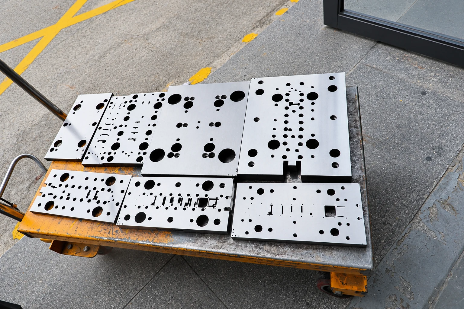
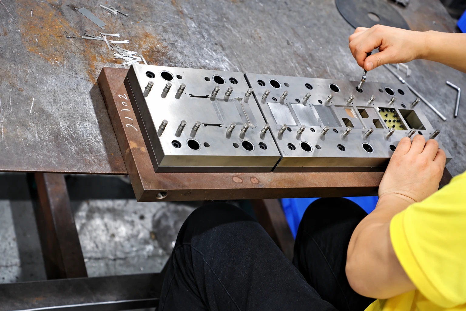
Paid samples include a full dimensional inspection report. Define drawing datums, acceptance criteria and corresponding mating parts so measurement and installed-fit checks can each answer the correct question. Confirm the charges, responsibilities and revision requirements for design changes, tooling work and later production stages within the project scope.
Paid samples and project planning
Samples are chargeable. Reference planning: standard samples 3–5 days; expedited sampling 48 hours; tooling and sample production 7–10 days. These are sample-stage arrangements, excluding mass-production delivery. The project plan is reviewed against the confirmed information, process and sample scope.
Related structures and project directions
Compare references through their coverage, installation and manufacturing tasks.
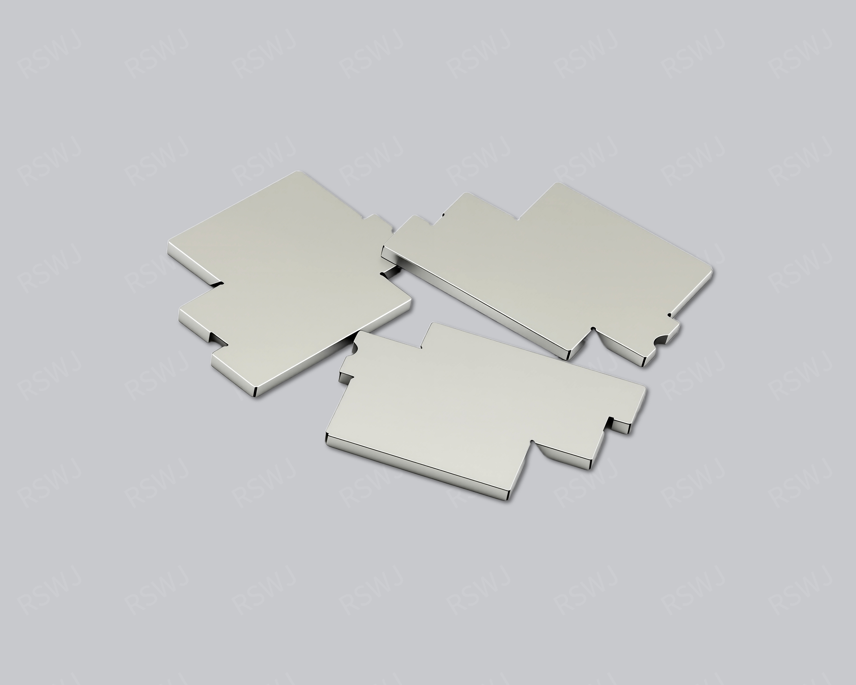
EMI Shielding Lid
A shielding lid closes the upper side of a frame or base and is defined with that mating structure.
Design & manufacturing details →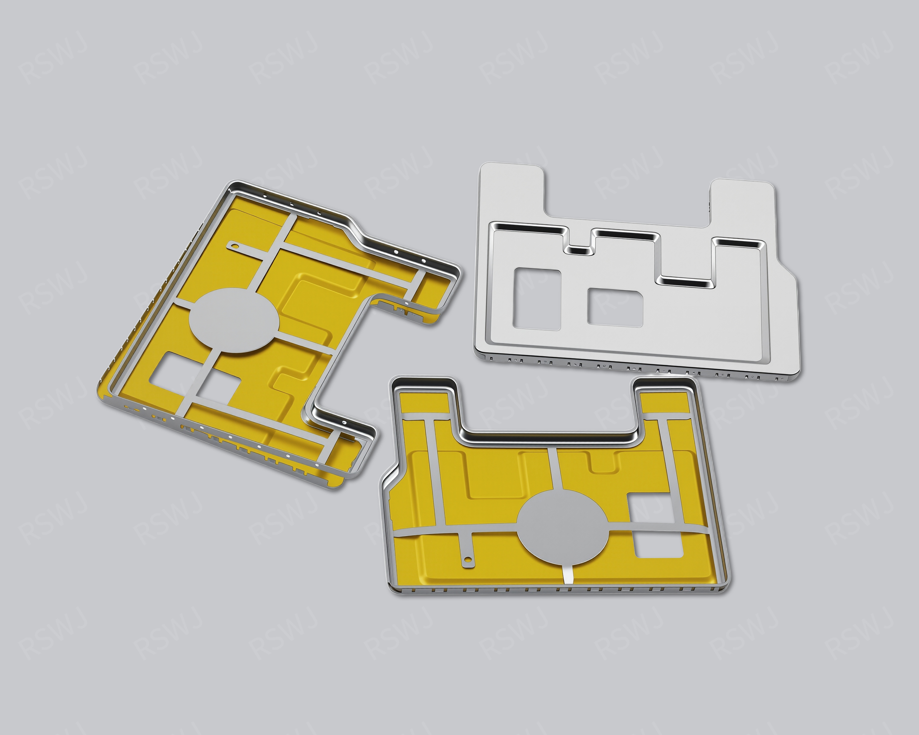
EMI Shielding Frame
A shielding frame connects a PCB attachment perimeter with the mating edge of a lid or other closure.
Design & manufacturing details →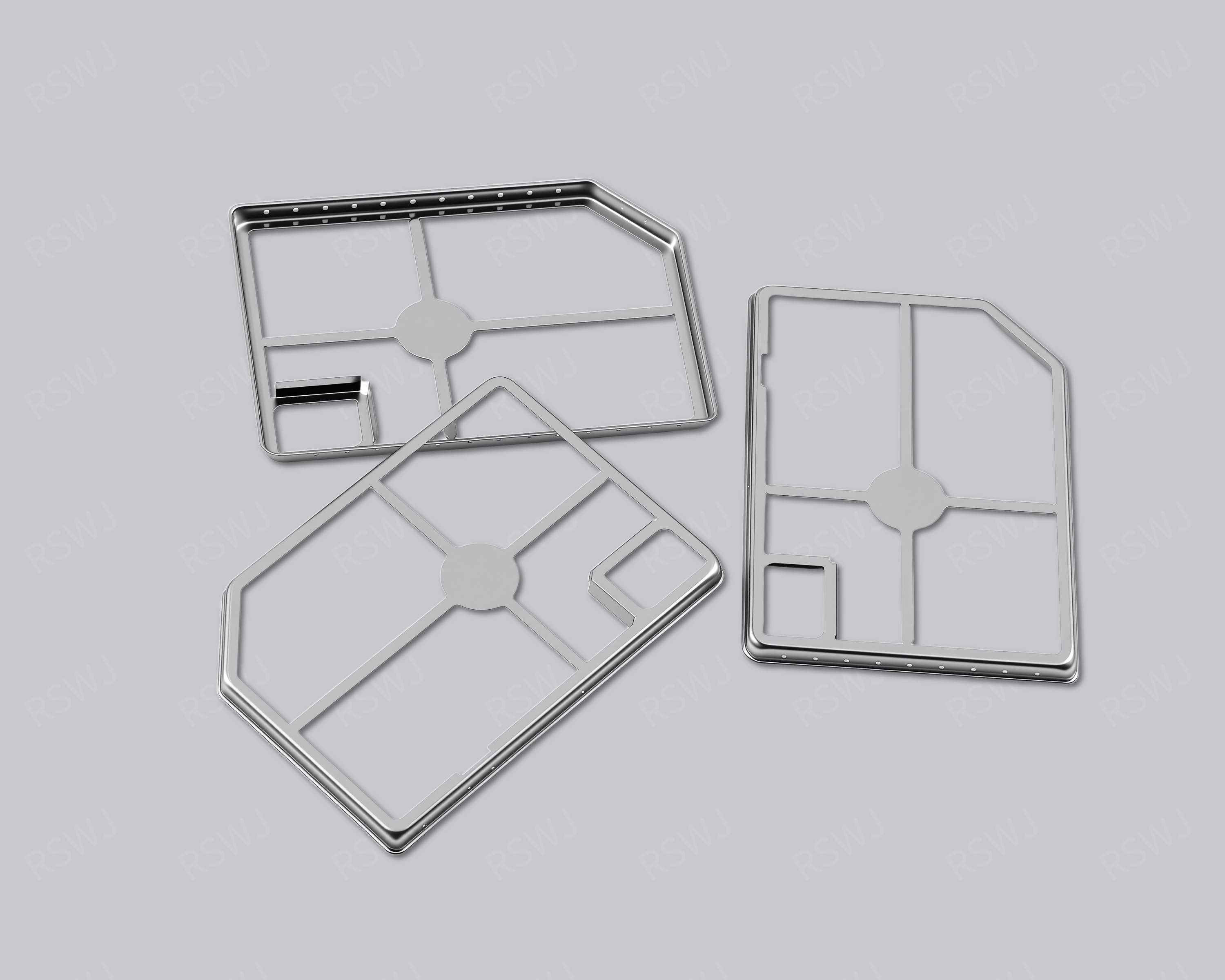
SMT Shielding Frame
An SMT shielding structure connects local coverage with surface-mount placement and attachment.
Design & manufacturing details →Discuss your Shielding Clip project
Send the current drawing and mating conditions so we can review the structure, material, sample scope and required checks.
Send your project requirementsExplore frames, lids & clips